SFI SYSTEM, Diagnostic DTC:P0261, P0262, P0264, P0265, P0267, P0268, P0270, P0271
| DTC Code | DTC Name |
|---|---|
| P0261 | Cylinder 1 Injector "A" Circuit Low |
| P0262 | Cylinder 1 Injector "A" Circuit High |
| P0264 | Cylinder 2 Injector "A" Circuit Low |
| P0265 | Cylinder 2 Injector "A" Circuit High |
| P0267 | Cylinder 3 Injector "A" Circuit Low |
| P0268 | Cylinder 3 Injector "A" Circuit High |
| P0270 | Cylinder 4 Injector "A" Circuit Low |
| P0271 | Cylinder 4 Injector "A" Circuit High |
DESCRIPTION
| DTC No. | Detection Item | DTC Detection Condition | Trouble Area | MIL | Memory |
|---|---|---|---|---|---|
| P0261 | Cylinder 1 Injector "A" Circuit Low | DTC Detection Condition
Enable Criteria
Malfunction Criteria
Diagnostic Mask
Monitor
Potential failure modes |
|
Comes on | DTC stored |
| P0262 | Cylinder 1 Injector "A" Circuit High | DTC Detection Condition
Enable Criteria
Malfunction Criteria
Diagnostic Mask
Monitor
Potential failure modes |
|
Comes on | DTC stored |
| P0264 | Cylinder 2 Injector "A" Circuit Low | DTC Detection Condition
Enable Criteria
Malfunction Criteria
Diagnostic Mask
Monitor
Potential failure modes |
|
Comes on | DTC stored |
| P0265 | Cylinder 2 Injector "A" Circuit High | DTC Detection Condition
Enable Criteria
Malfunction Criteria
Diagnostic Mask
Monitor
Potential failure modes |
|
Comes on | DTC stored |
| P0267 | Cylinder 3 Injector "A" Circuit Low | DTC Detection Condition
Enable Criteria
Malfunction Criteria
Diagnostic Mask
Monitor
Potential failure modes |
|
Comes on | DTC stored |
| P0268 | Cylinder 3 Injector "A" Circuit High | DTC Detection Condition
Enable Criteria
Malfunction Criteria
Diagnostic Mask
Monitor
Potential failure modes |
|
Comes on | DTC stored |
| P0270 | Cylinder 4 Injector "A" Circuit Low | DTC Detection Condition
Enable Criteria
Malfunction Criteria
Diagnostic Mask
Monitor
Potential failure modes |
|
Comes on | DTC stored |
| P0271 | Cylinder 4 Injector "A" Circuit High | DTC Detection Condition
Enable Criteria
Malfunction Criteria
Diagnostic Mask
Monitor
Potential failure modes |
|
Comes on | DTC stored |
Tech Tips
-
If DTC P0261 or P0262 is displayed, check No. 1 fuel injector assembly circuit.
-
If DTC P0264 or P0265 is displayed, check No. 2 fuel injector assembly circuit.
-
If DTC P0267 or P0268 is displayed, check No. 3 fuel injector assembly circuit.
-
If DTC P0270 or P0271 is displayed, check No. 4 fuel injector assembly circuit.
MONITOR DESCRIPTION
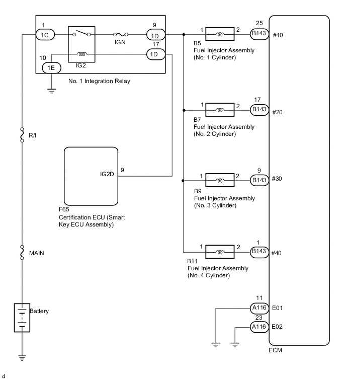
The ECU has four injector driver circuits, each of which controls an injector. When the engine is running the ECU continuously monitors the injector circuit feedback signals.
The monitored feedback signal should be low voltage when the injector is ON and high voltage when the injector is OFF.
WIRING DIAGRAM
CAUTION / NOTICE / HINT
Tech Tips
Read freeze frame data using the GTS. The ECM records vehicle and driving condition information as freeze frame data the moment a DTC is stored. When troubleshooting, freeze frame data can help determine if the vehicle was moving or stationary, if the engine was warmed up or not, if the air-fuel ratio was lean or rich, and other data from the time the malfunction occurred.
PROCEDURE
-
CHECK TERMINAL VOLTAGE (POWER SOURCE OF FUEL INJECTOR ASSEMBLY)
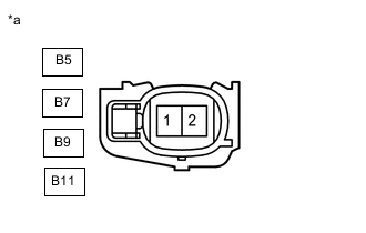
*a Front view of wire harness connector
(to Fuel Injector Assembly)
-
Disconnect the fuel injector assembly connectors.
-
Turn the engine switch on (IG).
-
Measure the voltage according to the value(s) in the table below.
Standard Voltage Tester Connection Switch Condition Specified Condition B5-1 - Body ground Engine switch on (IG) 11 to 14 V B7-1 - Body ground Engine switch on (IG) 11 to 14 V B9-1 - Body ground Engine switch on (IG) 11 to 14 V B11-1 - Body ground Engine switch on (IG) 11 to 14 V Result Proceed to OK NG
NG 
INSPECT NO. 1 INTEGRATION RELAY (IG2 RELAY) Click here
OK 
-
-
INSPECT FUEL INJECTOR ASSEMBLY (INJECTION AND VOLUME)
-
Inspect the fuel injector assembly.
Result Proceed to OK NG
NG 
REPLACE FUEL INJECTOR ASSEMBLY Click here
OK
-
-
CHECK HARNESS AND CONNECTOR (ECM - FUEL INJECTOR ASSEMBLY)
-
Disconnect the B5, B7, B9 and B11 fuel injector assembly connectors.
-
Disconnect the B143 ECM connector.
-
Measure the resistance according to the value(s) in the table below.
Standard Resistance Tester Connection Condition Specified Condition B143-25 (#10) - B5-2 Always Below 1 Ω B143-17 (#20) - B7-2 Always Below 1 Ω B143-9 (#30) - B9-2 Always Below 1 Ω B143-1 (#40) - B11-2 Always Below 1 Ω B143-25 (#10) or B5-2 - Body ground and other terminals Always 10 kΩ or higher B143-17 (#20) or B7-2 - Body ground and other terminals Always 10 kΩ or higher B143-9 (#30) or B9-2 - Body ground and other terminals Always 10 kΩ or higher B143-1 (#40) or B11-2 - Body ground and other terminals Always 10 kΩ or higher Result Proceed to OK NG
NG
REPAIR OR REPLACE HARNESS OR CONNECTOR
OK
-
-
CHECK HARNESS AND CONNECTOR (ECM - BODY GROUND)
-
Disconnect the A116 ECM connector.
-
Measure the resistance according to the value(s) in the table below.
Standard Resistance Tester Connection Condition Specified Condition A116-11 (E01) - Body ground Always Below 1 Ω A116-23 (E02) - Body ground Always Below 1 Ω Result Proceed to OK NG
OK
CHECK FOR INTERMITTENT PROBLEMS Click here
NG
REPAIR OR REPLACE HARNESS OR CONNECTOR
-
-
INSPECT NO. 1 INTEGRATION RELAY (IG2 RELAY)
-
Inspect the No. 1 integration relay.
Result Proceed to OK NG
OK
CHECK ECM POWER SOURCE CIRCUIT Click here
NG
REPLACE NO. 1 INTEGRATION RELAY Click here
-