SFI SYSTEM, Diagnostic DTC:P0222
| DTC Code | DTC Name |
|---|---|
| P0222 | Throttle / Pedal Position Sensor / Switch "B" Circuit Low |
DESCRIPTION
| DTC No. | Detection Item | DTC Detection Condition | Trouble Area | MIL | Memory |
|---|---|---|---|---|---|
| P0222 | Throttle / Pedal Position Sensor / Switch "B" Circuit Low | DTC Detection Condition
Enable Criteria
Malfunction Criteria
Diagnostic Mask
Monitor
Potential failure modes |
|
Comes on | DTC stored |
MONITOR DESCRIPTION
The throttle position sensor (TPS) is mounted on the throttle body, and detects the opening angle of the throttle valve. The TPS has 2 sensor circuits, each of which transmits a signal, VTA1 and VTA2. VTA1 is used to detect the throttle valve angle and VTA2 is used to detect malfunctions in VTA1. The sensor signal voltages vary between 0 V and 5 V in proportion to the throttle valve opening angle, and are transmitted to the VTA terminals of the ECU.
CAUTION / NOTICE / HINT
Tech Tips
Read freeze frame data using the GTS. The ECM records vehicle and driving condition information as freeze frame data the moment a DTC is stored. When troubleshooting, freeze frame data can help determine if the vehicle was moving or stationary, if the engine was warmed up or not, if the air fuel ratio was lean or rich, and other data from the time the malfunction occurred.
PROCEDURE
-
READ VALUE USING GTS (THROTTLE POSITION SENSOR)
-
Connect the GTS to the DLC3.
-
Turn the engine switch on (IG).
-
Turn the GTS on.
-
Enter the following menus: Powertrain / Engine / Data List / Gas Throttle / Throttle Position No.1 and Throttle Position No.2.
-
Read the values displayed on the GTS.
Result When Accelerator Pedal Fully Released When Accelerator Pedal Fully Depressed Trouble Area Proceed to Throttle Position No.1 (VTA1) Throttle Position No.2 (VTA2) Throttle Position No.1 (VTA1) Throttle Position No.2 (VTA2) 0 to 0.2 V 0 to 0.2 V 0 to 0.2 V 0 to 0.2 V VCTA circuit open A 4.5 to 4.98 V 4.5 to 4.98 V 4.5 to 4.98 V 4.5 to 4.98 V ETA circuit open 0 to 0.2 V, or 4.5 to 4.98 V 2.1 to 3.1 V (Fail-safe) 0 to 0.2 V, or 4.5 to 4.98 V 2.1 to 3.1 V (Fail-safe) VTA1 circuit open or shorted to ground 0.6 to 1.4 V (Fail-safe) 0 to 0.2 V, or 4.5 to 4.98 V 0.6 to 1.4 V (Fail-safe) 0 to 0.2 V, or 4.5 to 4.98 V VTA2 circuit open or shorted to ground 0.5 to 1.1 V 2.1 to 3.1 V 3.2 to 4.8 V (Not fail-safe) 4.6 to 4.98 V (Not fail-safe) Throttle position sensor circuit normal B
B 
CHECK WHETHER DTC OUTPUT RECURS (THROTTLE POSITION SENSOR DTCS) Click here
A 
-
-
CHECK HARNESS AND CONNECTOR (THROTTLE POSITION SENSOR - ECM)
-
Disconnect the B29 throttle body with motor assembly connector.
-
Disconnect the B142 ECM connector.
-
Measure the resistance according to the value(s) in the table below.
Standard Resistance Tester Connection Condition Specified Condition B29-5 (VC) - B142-5 (VCTA) Always Below 1 Ω B29-6 (VTA) - B142-30 (VTA1) Always Below 1 Ω B29-4 (VTA2) - B142-18 (VTA2) Always Below 1 Ω B29-3 (E2) - B142-3 (ETA) Always Below 1 Ω B29-5 (VC) or B142-5 (VCTA) - Body ground and other terminals Always 10 kΩ or higher B29-6 (VTA) or B142-30 (VTA1) - Body ground and other terminals Always 10 kΩ or higher B29-4 (VTA2) or B142-18 (VTA2) - Body ground and other terminals Always 10 kΩ or higher Result Proceed to OK NG
NG 
REPAIR OR REPLACE HARNESS OR CONNECTOR
OK
-
-
CHECK TERMINAL VOLTAGE (POWER SOURCE OF THROTTLE BODY WITH MOTOR ASSEMBLY)
-
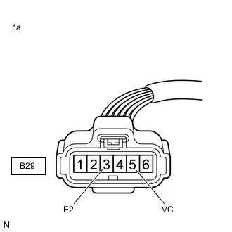
*a Front view of wire harness connector
(to Throttle Body with Motor Assembly)
Disconnect the throttle body with motor assembly connector.
-
Turn the engine switch on (IG).
-
Measure the voltage according to the value(s) in the table below.
Standard Voltage Tester Connection Switch Condition Specified Condition B29-5 (VC) - B29-3 (E2) Engine switch on (IG) 4.5 to 5.5 V Result Proceed to OK NG
NG
REPLACE ECM Click here
OK
-
-
REPLACE THROTTLE BODY WITH MOTOR ASSEMBLY
-
Replace the throttle body with motor assembly.
Tech Tips
Perform "Inspection After Repair" after replacing the throttle body with motor assembly.
Result Proceed to NEXT
NEXT
-
-
CHECK WHETHER DTC OUTPUT RECURS (THROTTLE POSITION SENSOR DTCS)
-
Connect the GTS to the DLC3.
-
Turn the engine switch on (IG).
-
Turn the GTS on.
-
Clear the DTCs.
-
Turn the engine switch off and wait for at least 30 seconds.
-
Turn the engine switch on (IG).
-
Turn the GTS on.
-
Enter the following menus: Powertrain / Engine / Trouble Codes.
-
Read the DTCs.
Result Result Proceed to DTC P0222are output A DTCs are not output B
A
REPLACE ECM Click here
B
END
-