SFI SYSTEM, Diagnostic DTC:P0444
| DTC Code | DTC Name |
|---|---|
| P0444 | EVAP System Purge Control Valve "A" Circuit Open |
DESCRIPTION
| DTC No. | Detection Item | DTC Detection Condition | Trouble Area | MIL | Memory |
|---|---|---|---|---|---|
| P0444 | EVAP System Purge Control Valve "A" Circuit Open | DTC Detection Condition
Enable Criteria
Malfunction Criteria
Diagnostic Mask
Monitor
Potential failure modes |
|
Comes on | DTC stored |
MONITOR DESCRIPTION
When the engine is running the ECU continuously monitors the status of the evaporative emission components for open circuit or short to. The feedback signal should be low when turned ON and high when turned OFF. The following codes will be set if the above conditions are not met.
WIRING DIAGRAM
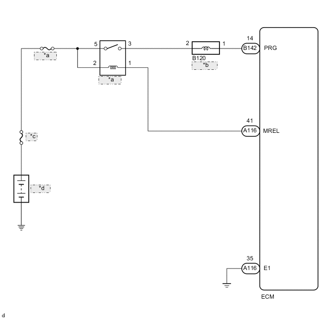
| *a | EFI MAIN |
| *b | Purge VSV |
| *c | MAIN |
| *d | Battery |
CAUTION / NOTICE / HINT
Note
Inspect the fuses for circuits related to this system before performing the following procedure.
Tech Tips
Read freeze frame data using the GTS. The ECM records vehicle and driving condition information as freeze frame data the moment a DTC is stored. When troubleshooting, freeze frame data can help determine if the vehicle was moving or stationary, if the engine was warmed up or not, if the air fuel ratio was lean or rich, and other data from the time the malfunction occurred.
PROCEDURE
-
PERFORM ACTIVE TEST USING GTS (ACTIVATE THE VSV FOR EVAP CONTROL)
-
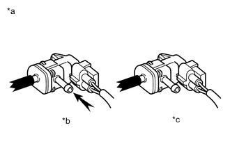
*a Reference *b VSV ON *c VSV OFF Disconnect the fuel vapor feed hose (charcoal canister side) of the purge VSV.
-
Connect the GTS to the DLC3.
-
Start the engine.
-
Turn the GTS on.
-
Enter the following menus: Powertrain / Engine / Active Test / Activate the VSV for Evap Control.
-
When the purge VSV is operated using the GTS, check whether the port of the purge VSV applies suction your finger.
OK GTS Operation Specified Condition ON Purge VSV port applies suction to finger OFF Purge VSV port applies no suction to finger Result Proceed to OK NG
OK 
CHECK FOR INTERMITTENT PROBLEMS Click here
NG 
-
-
INSPECT PURGE VSV
-
Inspect the purge VSV.
Result Proceed to OK NG
NG
REPLACE PURGE VSV Click here
OK
-
-
CHECK TERMINAL VOLTAGE (POWER SOURCE OF PURGE VSV)
-
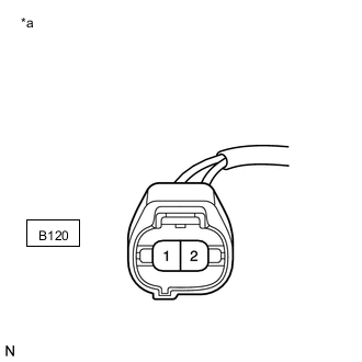
*a Front view of wire harness connector
(to Purge VSV)
Disconnect the purge VSV connector.
-
Turn the engine switch on (IG).
-
Measure the voltage according to the value(s) in the table below.
Standard Voltage Tester Connection Switch Condition Specified Condition B120-2 - Body ground Engine switch on (IG) 11 to 14 V Result Proceed to OK NG
NG 
INSPECT EFI MAIN RELAY Click here
OK
-
-
CHECK HARNESS AND CONNECTOR (PURGE VSV - ECM)
-
Disconnect the B120 purge VSV connector.
-
Disconnect the B142 ECM connector.
-
Measure the resistance according to the value(s) in the table below.
Standard Resistance Tester Connection Condition Specified Condition B120-1 - B142-14 (PRG) Always Below 1 Ω B120-1 or B142-14 (PRG) - Body ground and other terminals Always 10 kΩ or higher Result Proceed to OK NG
OK
REPLACE ECM Click here
NG
REPAIR OR REPLACE HARNESS OR CONNECTOR
-
-
INSPECT EFI MAIN RELAY
-
Inspect the EFI MAIN relay.
Result Proceed to OK NG
NG
REPLACE EFI MAIN RELAY
OK
-
-
CHECK HARNESS AND CONNECTOR (EFI MAIN RELAY - PURGE VSV)
-
Remove the EFI MAIN relay from the No. 2 engine room relay block assembly.
-
Disconnect the B120 purge VSV connector.
-
Measure the resistance according to the value(s) in the table below.
Standard Resistance Tester Connection Condition Specified Condition 3 (EFI MAIN relay holder) - B120-2 Always Below 1 Ω 3 (EFI MAIN relay holder) or B120-2 - Body ground and other terminals Always 10 kΩ or higher Result Proceed to OK NG
OK
CHECK ECM POWER SOURCE CIRCUIT Click here
NG
REPAIR OR REPLACE HARNESS OR CONNECTOR
-