THROTTLE BODY INSTALLATION
PROCEDURE
-
INSTALL THROTTLE BODY GASKET
-
Install a new throttle body gasket to the intake manifold.
Note
Check that the gasket is securely fitted into the groove on the intake manifold.
-
-
INSTALL THROTTLE BODY WITH MOTOR ASSEMBLY
-
Temporarily install the throttle body with motor assembly to the intake manifold with the 3 bolts.
Note
If the throttle body with motor assembly has been struck or dropped, replace it.
-
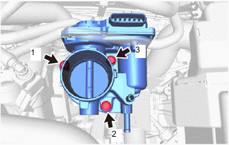
Tighten the 3 bolts in the order shown in the illustration.
- Torque:
- 15 N*m { 153 kgf*cm, 11 ft.*lbf }
-
Connect the throttle body with motor assembly connector.
-
-
CONNECT WATER BY-PASS HOSE
-
Connect the water by-pass hose to the throttle body with motor assembly and slide the hose clip to secure it.
-
-
CONNECT NO. 2 WATER BY-PASS HOSE
-
Connect the No. 2 water by-pass hose to the throttle body with motor assembly and slide the hose clip to secure it.
-
-
INSTALL AIR CLEANER HOSE ASSEMBLY
-
Connect the air cleaner hose assembly to the throttle body with motor assembly and unlock the hose clip to secure it.
-
Connect the air cleaner hose assembly to the air cleaner cap sub-assembly and tighten the hose clamp.
- Torque:
- 3.0 N*m { 31 kgf*cm, 27 in.*lbf }
-
Engage the clamp to connect the No. 2 fuel vapor feed hose assembly to the air cleaner hose assembly.
-
-
CONNECT NO. 1 AIR HOSE (for CVT)
-
Connect the No. 1 air hose to the air cleaner hose assembly and slide the hose clip to secure it.
-
-
INSTALL NO. 2 VACUUM SWITCHING VALVE ASSEMBLY (for CVT)
-
Install the No. 2 vacuum switching valve assembly to the air cleaner hose assembly.
-
-
CONNECT NO. 2 VENTILATION HOSE
-
Engage the clamp to connect the No. 2 ventilation hose to the engine wire.
-
Connect the No. 2 ventilation hose to the cylinder head sub-assembly and slide the hose clip to secure it.
-
-
ADD ENGINE COOLANT
-
INSPECT FOR COOLANT LEAK
-
INSTALL OUTER COWL TOP PANEL
-
for LHD:
-
for RHD:
-
-
INSTALL INNER COWL TOP TO COWL BRACE
-
for LHD:
-
for RHD:
-
-
INSTALL FRONT NO. 1 VENTILATOR SEAL
-
for LHD:
-
for RHD:
-
-
INSTALL FRONT AIR SHUTTER SEAL RH
-
for LHD:
-
for RHD:
-
-
INSTALL WINDSHIELD WIPER MOTOR AND LINK
-
PERFORM INITIALIZATION
Note
-
Be sure to perform this procedure after removing and reinstalling the throttle with motor body assembly or any throttle with motor body assembly components.
-
Perform the following procedure after replacing the throttle with motor body assembly or any throttle with motor body assembly components. The following procedure should also be performed if the throttle body with motor assembly is cleaned.
-
Connect the GTS to the DLC3.
-
Clear the DTCs.
-
Perform "Inspection After Repair".
-
Start the engine and check that the MIL is not illuminated. After the engine is warmed up, check that the idle speed is within the specified range with the A/C switch off.
Standard Idle Speed for Manual Transaxle 550 to 650 rpm for CVT 680 to 780 rpm Note
-
Be sure to perform this step with all accessories off.
-
Make sure that the shift lever is in N or P.
-
-
Enter the following menus: Powertrain / Engine and ECT / Data List / All Data / Throttle Sensor Position.
Powertrain > Engine > Data ListTester Display Throttle Sensor Position -
Fully depress the accelerator pedal and check that the value of Throttle Sensor Position is 60% or higher.
-
Perform a road test and confirm that there are no abnormalities.
-