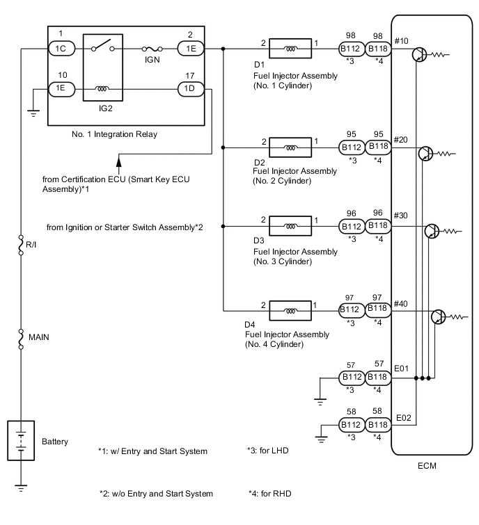
SFI SYSTEM Fuel Injector Circuit
DESCRIPTION
They inject fuel into the cylinders based on signals from the ECM.
WIRING DIAGRAM
CAUTION / NOTICE / HINT
Note
Inspect the fuses for circuits related to this system before performing the following procedure.
PROCEDURE
-
CHECK TERMINAL VOLTAGE (POWER SOURCE OF FUEL INJECTOR ASSEMBLY)
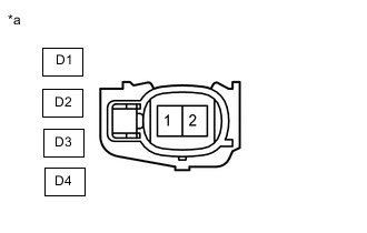
*a Front view of wire harness connector
(to Fuel Injector Assembly)
-
Disconnect the fuel injector assembly connectors.
-
Turn the ignition switch to ON.
-
Measure the voltage according to the value(s) in the table below.
Standard Voltage Tester Connection Switch Condition Specified Condition D1-2 - Body ground Ignition switch ON 11 to 14 V D2-2 - Body ground Ignition switch ON 11 to 14 V D3-2 - Body ground Ignition switch ON 11 to 14 V D4-2 - Body ground Ignition switch ON 11 to 14 V Result Proceed to OK NG
NG 
CHECK HARNESS AND CONNECTOR (NO. 1 INTEGRATION RELAY - FUEL INJECTOR ASSEMBLY) Click here
OK 
-
-
INSPECT FUEL INJECTOR ASSEMBLY (INJECTION AND VOLUME)
-
Inspect the fuel injector assembly.
Result Proceed to OK NG
NG 
REPLACE FUEL INJECTOR ASSEMBLY Click here
OK
-
-
CHECK HARNESS AND CONNECTOR (ECM - FUEL INJECTOR ASSEMBLY)
-
Disconnect the D1, D2, D3 and D4 fuel injector assembly connectors.
-
Disconnect the B112 ECM connector.*1
-
Disconnect the B118 ECM connector.*2
-
Measure the resistance according to the value(s) in the table below.
*1: for LHD
*2: for RHD
Standard Resistance for LHD Tester Connection Condition Specified Condition B112-98 (#10) - D1-1 Always Below 1 Ω B112-95 (#20) - D2-1 Always Below 1 Ω B112-96 (#30) - D3-1 Always Below 1 Ω B112-97 (#40) - D4-1 Always Below 1 Ω B112-98 (#10) or D1-1 - Body ground and other terminals Always 10 kΩ or higher B112-95 (#20) or D2-1 - Body ground and other terminals Always 10 kΩ or higher B112-96 (#30) or D3-1 - Body ground and other terminals Always 10 kΩ or higher B112-97 (#40) or D4-1 - Body ground and other terminals Always 10 kΩ or higher for RHD Tester Connection Condition Specified Condition B118-98 (#10) - D1-1 Always Below 1 Ω B118-95 (#20) - D2-1 Always Below 1 Ω B118-96 (#30) - D3-1 Always Below 1 Ω B118-97 (#40) - D4-1 Always Below 1 Ω B118-98 (#10) or D1-1 - Body ground and other terminals Always 10 kΩ or higher B118-95 (#20) or D2-1 - Body ground and other terminals Always 10 kΩ or higher B118-96 (#30) or D3-1 - Body ground and other terminals Always 10 kΩ or higher B118-97 (#40) or D4-1 - Body ground and other terminals Always 10 kΩ or higher Result Proceed to OK NG
NG
REPAIR OR REPLACE HARNESS OR CONNECTOR
OK
-
-
CHECK HARNESS AND CONNECTOR (ECM - BODY GROUND)
-
Disconnect the B112 ECM connector.*1
-
Disconnect the B118 ECM connector.*2
-
Measure the resistance according to the value(s) in the table below.
*1: for LHD
*2: for RHD
Standard Resistance for LHD Tester Connection Condition Specified Condition B112-57 (E01) - Body ground Always Below 1 Ω B112-58 (E02) - Body ground Always Below 1 Ω for RHD Tester Connection Condition Specified Condition B118-57 (E01) - Body ground Always Below 1 Ω B118-58 (E02) - Body ground Always Below 1 Ω Result Proceed to OK NG
OK
PROCEED TO NEXT SUSPECTED AREA SHOWN IN PROBLEM SYMPTOMS TABLE Click here
NG
REPAIR OR REPLACE HARNESS OR CONNECTOR
-
-
CHECK HARNESS AND CONNECTOR (NO. 1 INTEGRATION RELAY - FUEL INJECTOR ASSEMBLY)
-
Disconnect the No. 1 integration relay connector.
-
Disconnect the D1, D2, D3 and D4 fuel injector assembly connectors.
-
Measure the resistance according to the value(s) in the table below.
Standard Resistance Tester Connection Condition Specified Condition 1E-2 - D1-2 Always Below 1 Ω 1E-2 - D2-2 Always Below 1 Ω 1E-2 - D3-2 Always Below 1 Ω 1E-2 - D4-2 Always Below 1 Ω 1E-2 or D1-2 - Body ground and other terminals Always 10 kΩ or higher 1E-2 or D2-2 - Body ground and other terminals Always 10 kΩ or higher 1E-2 or D3-2 - Body ground and other terminals Always 10 kΩ or higher 1E-2 or D4-2 - Body ground and other terminals Always 10 kΩ or higher Result Proceed to OK NG
OK
CHECK ECM POWER SOURCE CIRCUIT Click here
NG
REPAIR OR REPLACE HARNESS OR CONNECTOR
-