SFI SYSTEM VC Output Circuit
DESCRIPTION
The ECM constantly generates a 5 V power source voltage from the battery voltage supplied to the +B, +B2 (BATT) terminals to operate the microprocessor. The ECM also provides this power source voltage to the sensors through the VC output circuit.
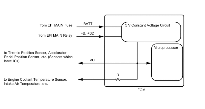
When the VC circuit is short-circuited, the microprocessor in the ECM and the sensors that are supplied with power through the VC circuit are inactivated because power is not supplied from the VC circuit. Under this condition, the system does not start up and the MIL does not illuminate even if the system malfunctions.
Tech Tips
Under normal conditions, the MIL is illuminated when the ignition switch is turned to ON. The MIL goes off when the engine is started.
CAUTION / NOTICE / HINT
Note
Check the fuses for circuits related to this system before performing the following inspection procedure.
PROCEDURE
-
CHECK MIL
-
Check that the Malfunction Indicator Lamp (MIL) lights up when the ignition switch is turned to ON.
OK MIL lights up. Result Proceed to OK NG
OK 
PROCEED TO NEXT SUSPECTED AREA SHOWN IN PROBLEM SYMPTOMS TABLE Click here
NG 
-
-
CHECK COMMUNICATION BETWEEN GTS AND ECM
-
Connect the GTS to the DLC3.
-
Turn the ignition switch to ON.
-
Turn the GTS on.
-
Check for communication between the GTS and ECM.
Result Result Proceed to Communication is not possible A Communication is possible B
B
CHECK ECU POWER SOURCE CIRCUIT
A
-
-
CHECK MIL (THROTTLE POSITION SENSOR)
-
Disconnect the B29 throttle body with motor assembly connector.
-
Turn the ignition switch to ON.
-
Turn the GTS on.
-
Check the communication between the GTS and ECM.
Tech Tips
The Data List item "Engine and ECT" can be checked.
Result Result Proceed to MIL does not illuminate A MIL illuminates B Tech Tips
Perform "Inspection After Repair" after replacing the throttle body with motor assembly.
B
REPLACE THROTTLE BODY WITH MOTOR ASSEMBLY Click here
A
-
-
CHECK MIL (ACCELERATOR PEDAL POSITION SENSOR)
-
Disconnect the A36 accelerator pedal sensor assembly connector.
-
Turn the ignition switch to ON.
-
Turn the GTS on.
-
Check the communication between the GTS and ECM.
Tech Tips
The Data List item "Engine and ECT" can be checked.
Result Result Proceed to MIL does not illuminate A MIL illuminates B
B
REPLACE ACCELERATOR PEDAL SENSOR ASSEMBLY Click here
A
-
-
CHECK MIL (CAMSHAFT POSITION SENSOR (FOR INTAKE CAMSHAFT))
-
Disconnect the B32 camshaft position sensor (for intake camshaft) connector.
-
Turn the ignition switch to ON.
-
Turn the GTS on.
-
Check the communication between the GTS and ECM.
Tech Tips
The Data List item "Engine and ECT" can be checked.
Result Result Proceed to MIL does not illuminate A MIL illuminates B
B
REPLACE CAMSHAFT POSITION SENSOR (FOR INTAKE CAMSHAFT) Click here
A
-
-
CHECK MIL (CAMSHAFT POSITION SENSOR (FOR EXHAUST CAMSHAFT))
-
Disconnect the B31 camshaft position sensor (for exhaust camshaft) connector.
-
Turn the ignition switch to ON.
-
Turn the GTS on.
-
Check the communication between the GTS and ECM.
Tech Tips
The Data List item "Engine and ECT" can be checked.
Result Result Proceed to MIL does not illuminate A MIL illuminates B
B
REPLACE CAMSHAFT POSITION SENSOR (FOR EXHAUST CAMSHAFT) Click here
A
-
-
CHECK MIL (CRANKSHAFT POSITION SENSOR)
-
Disconnect the B24 crankshaft position sensor connector.
-
Turn the ignition switch to ON.
-
Turn the GTS on.
-
Check the communication between the GTS and ECM.
Tech Tips
The Data List item "Engine and ECT" can be checked.
Result Result Proceed to MIL does not illuminate A MIL illuminates B
B
REPLACE CRANKSHAFT POSITION SENSOR Click here
A
-
-
CHECK MIL (VACUUM SENSOR (MANIFOLD ABSOLUTE PRESSURE SENSOR))
-
Disconnect the B91 vacuum sensor (manifold absolute pressure sensor) connector.
-
Turn the ignition switch to ON.
-
Turn the GTS on.
-
Check the communication between the GTS and ECM.
Tech Tips
The Data List item "Engine and ECT" can be checked.
Result Result Proceed to MIL does not illuminate A MIL illuminates B
B
REPLACE VACUUM SENSOR (MANIFOLD ABSOLUTE PRESSURE SENSOR) Click here
A
-
-
CHECK MIL (VACUUM SENSOR ASSEMBLY)
-
Disconnect the A33 vacuum sensor assembly connector.
-
Turn the ignition switch to ON.
-
Turn the GTS on.
-
Check the communication between the GTS and ECM.
Tech Tips
The Data List item "Engine and ECT" can be checked.
Result Result Proceed to MIL does not illuminate*1 A MIL does not illuminate*2 B MIL illuminates C
-
*1: for CVT
-
*2: for Manual Transaxle
-
B 
CHECK MIL (BATTERY STATE SENSOR) Click here
C
REPLACE VACUUM SENSOR ASSEMBLY Click here
A
-
-
CHECK MIL (OIL PRESSURE SENSOR)
-
Disconnect the B45 oil pressure sensor connector.
-
Turn the ignition switch to ON.
-
Turn the GTS on.
-
Check the communication between the GTS and ECM.
Tech Tips
The Data List item "Engine and ECT" can be checked.
Result Result Proceed to MIL does not illuminate A MIL illuminates B
B
REPLACE OIL PRESSURE SENSOR Click here
A
-
-
CHECK MIL (BATTERY STATE SENSOR)
-
Disconnect the A31 battery state sensor connector.
-
Turn the ignition switch to ON.
-
Turn the GTS on.
-
Check the communication between the GTS and ECM.
Tech Tips
The Data List item "Engine and ECT" can be checked.
Result Result Proceed to MIL does not illuminate*1 A MIL does not illuminate*2 B MIL illuminates C
-
*1: w/ Stop and Start System
-
*2: w/o Stop and Start System
-
A
GO TO STEP 13 Click here
C
REPLACE BATTERY CURRENT SENSOR Click here
B
-
-
CHECK MIL (ATMOSPHERIC PRESSURE SENSOR)
-
Disconnect the F137 atmospheric pressure sensor connector.
-
Turn the ignition switch to ON.
-
Turn the GTS on.
-
Check the communication between the GTS and ECM.
Tech Tips
The Data List item "Engine and ECT" can be checked.
Result Result Proceed to MIL does not illuminate A MIL illuminates B
B
REPLACE ATMOSPHERIC PRESSURE SENSOR
A
-
-
CHECK HARNESS AND CONNECTOR
-
Disconnect the B29 throttle body with motor assembly connector.
-
Disconnect the A36 accelerator pedal sensor assembly connector.
-
Disconnect the B32 camshaft position sensor (for intake camshaft) connector.
-
Disconnect the B31 camshaft position sensor (for exhaust camshaft) connector.
-
Disconnect the B24 crankshaft position sensor connector.
-
Disconnect the B91 vacuum sensor (manifold absolute pressure sensor) connector.
-
Disconnect the A33 vacuum sensor assembly connector.
-
Disconnect the B45 oil pressure sensor connector.*1
-
Disconnect the A31 battery state sensor assembly connector.*2
-
Disconnect the F137 atmospheric pressure sensor connector.*2
-
Disconnect the A58 and B112 ECM connectors.*3
-
Disconnect the A58 and B118 ECM connectors.*4
-
Measure the resistance according to the value(s) in the table below.
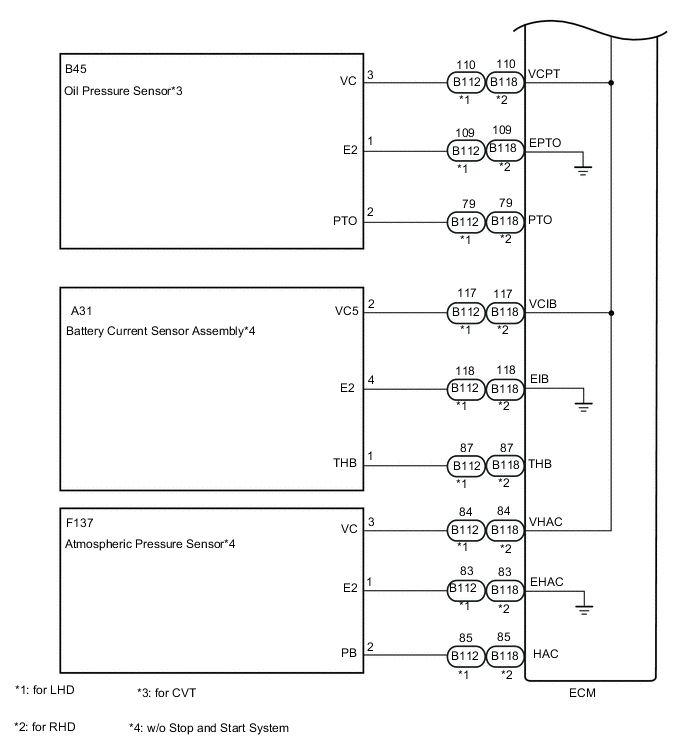
*1: for CVT
*2: w/o Stop and Start System
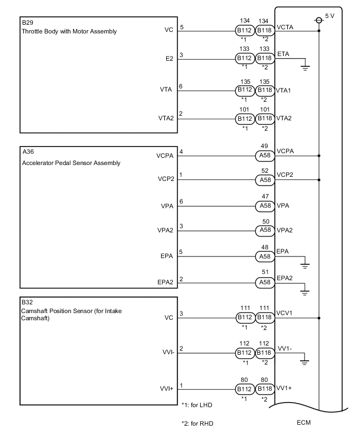
*3: for LHD
*4: for RHD
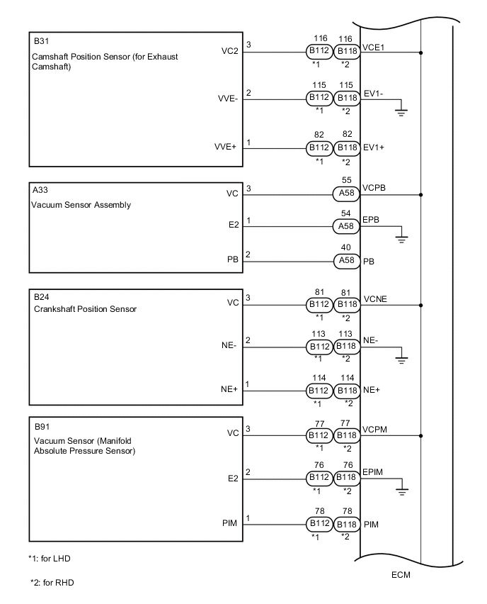
Standard Resistance for LHD Tester Connection Condition Specified Condition B112-134 (VCTA) - Body ground and other terminals Always 10 kΩ or higher A58-49 (VCPA) - Body ground and other terminals Always 10 kΩ or higher A58-52 (VCP2) - Body ground and other terminals Always 10 kΩ or higher B112-111 (VCV1) - Body ground and other terminals Always 10 kΩ or higher B112-116 (VCE1) - Body ground and other terminals Always 10 kΩ or higher B112-81 (VCNE) - Body ground and other terminals Always 10 kΩ or higher B112-77 (VCPM) - Body ground and other terminals Always 10 kΩ or higher A58-55 (VCPB) - Body ground and other terminals Always 10 kΩ or higher B112-110 (VCPT) - Body ground and other terminals*1 Always 10 kΩ or higher B112-117 (VCIB) - Body ground and other terminals*2 Always 10 kΩ or higher B112-84 (VHAC) - Body ground and other terminals*2 Always 10 kΩ or higher for RHD Tester Connection Condition Specified Condition B118-134 (VCTA) - Body ground Always 10 kΩ or higher A58-49 (VCPA) - Body ground Always 10 kΩ or higher A58-52 (VCP2) - Body ground Always 10 kΩ or higher B118-111 (VCV1) - Body ground Always 10 kΩ or higher B118-116 (VCE1) - Body ground Always 10 kΩ or higher B118-81 (VCNE) - Body ground Always 10 kΩ or higher B118-77 (VCPM) - Body ground Always 10 kΩ or higher A58-55 (VCPB) - Body ground Always 10 kΩ or higher B118-110 (VCPT) - Body ground Always 10 kΩ or higher B118-117 (VCIB) - Body ground Always 10 kΩ or higher B118-84 (VHAC) - Body ground Always 10 kΩ or higher
-
*1: for CVT
-
*2: w/o Stop and Start System
Result Proceed to OK NG -
OK
REPLACE ECM Click here
NG
REPAIR OR REPLACE HARNESS OR CONNECTOR
-