VACUUM SENSOR ON-VEHICLE INSPECTION
PROCEDURE
-
INSPECT VACUUM SENSOR ASSEMBLY (w/ Stop And Start System)
-
Inspect the brake booster.
-
for LHD:
-
for RHD:
-
-
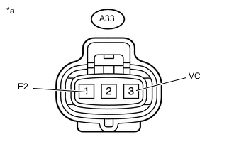
*a Front view of wire harness connector
(Vacuum Sensor Assembly)
Inspect the power source voltage.
-
Disconnect the vacuum sensor assembly connector.
-
Turn the ignition switch to ON.
-
Measure the voltage according to the value(s) in the table below.
Standard Voltage Tester Connection Switch Condition Specified Condition A33-3 (VC) - A33-1 (E2) Ignition Switch ON 4.75 to 5.25 V If the result is not as specified, check the harness, connector, and engine stop and start ECU.
-
Turn the ignition switch off.
-
Connect the vacuum sensor assembly connector.
-
-
Inspect the atmospheric pressure voltage.
-
Depress the brake pedal 5 times.
-
Measure the PB terminal voltage at the engine stop and start ECU according to the value(s) in the table below.
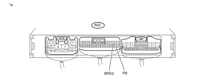
*a Component with harness connected
(Engine Stop and Start ECU)
- - Standard Voltage Tester Connection Condition Specified Condition A92-13 (PB) - A92-3 (BRE2) Atmospheric pressure 3.4 to 3.8 V If the result is not as specified, check the harness and connector.
-
-
Inspect the brake negative pressure.
-
Start the engine. Wait for several minutes and stop the engine by turning the ignition switch off.
-
Connect the GTS to the DLC3.
-
Turn the ignition switch to ON.
-
Turn the GTS on.
-
Enter the following menus: Powertrain /Stop and Start / Data List / Brake Boost Pressure.
-
Depress the brake pedal 5 times and read the changes in the following pressure value.
Tech Tips
The changes in the value can be determined by comparing the pressure value before and after the brake pedal is depressed 5 times.
Standard Tester Display Switch Condition Specified Condition Brake Boost Pressure
-
Ignition switch ON
-
Brake pedal depressed 5 times
Changes by 20 kPa (150 mmHg, 6 in.Hg) or more If the result is not as specified, check the harness and connector.
-
-
-
-
INSPECT VACUUM SENSOR ASSEMBLY (w/o Stop And Start System)
-
Inspect the brake booster.
-
for LHD:
-
for RHD:
-
-
*a Front view of wire harness connector
(Vacuum Sensor Assembly)
Inspect the power source voltage.
-
Disconnect the vacuum sensor assembly connector.
-
Turn the ignition switch to ON.
-
Measure the voltage according to the value(s) in the table below.
Standard Voltage Tester Connection Switch Condition Specified Condition A33-3 (VC) - A33-1 (E2) Ignition Switch ON 4.75 to 5.25 V If the result is not as specified, check the harness, connector, and ECM.
-
Turn the ignition switch off.
-
Connect the vacuum sensor assembly connector.
-
-
Inspect the atmospheric pressure voltage.
-
Depress the brake pedal 5 times.
-
Measure the PB terminal voltage at the ECM according to the value(s) in the table below.
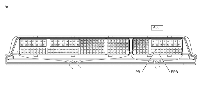
*a Component with harness connected
(ECM)
- - Standard Voltage Tester Connection Condition Specified Condition A58-40 (PB) - A58-54 (EPB) Atmospheric pressure 1.5 to 2.0 V If the result is not as specified, check the harness and connector.
-
-
Inspect the brake negative pressure.
-
Start the engine. Wait for several minutes and stop the engine by turning the ignition switch off.
-
Connect the GTS to the DLC3.
-
Turn the ignition switch to ON.
-
Turn the GTS on.
-
Enter the following menus: Powertrain / Engine and ECT / Data List / Brake Boost Pressure.
-
Depress the brake pedal 5 times and read the changes in the following pressure value.
Tech Tips
The changes in the value can be determined by comparing the pressure value before and after the brake pedal is depressed 5 times.
Standard Tester Display Switch Condition Specified Condition Brake Boost Pressure
-
Ignition switch ON
-
Brake pedal depressed 5 times
Changes by 20 kPa (150 mmHg, 6 in.Hg) or more If the result is not as specified, check the harness and connector.
-
-
-