SFI SYSTEM, Diagnostic DTC:P0500
| DTC Code | DTC Name |
|---|---|
| P0500 | Vehicle Speed Sensor |
DESCRIPTION
Vehicles, which are equipped with ABS (Anti-lock Brake System), detect the vehicle speed using the skid control ECU (brake actuator assembly) and speed sensor. The speed sensor monitors the wheel rotation speed and sends a signal to the skid control ECU. The skid control ECU converts the wheel speed signal into a 4-pulse signal and transmits it to the ECM via the combination meter assembly. The ECM determines the vehicle speed based on the frequency of the pulse signal.
Tech Tips
-
Various systems use the vehicle speed signal distributed from the combination meter assembly. Check all the components possibly related to the speed signal.
-
A voltage of 12 V or 5 V is output from each ECU and then input to the combination meter assembly.
The signal is changed to a pulse signal at the transistor in the combination meter assembly. Each ECU controls its respective system based on this pulse signal.
-
If a short occurs in any of the ECUs or in the wire harness connected to an ECU, all systems using the speed signal will not operate normally.
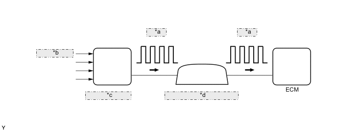
| *a | 4-Pulse |
| *b | from Speed Sensor |
| *c | Skid Control ECU |
| *d | Combination Meter Assembly |
| DTC No. | Detection Item | DTC Detection Condition | Trouble Area | MIL | Memory |
|---|---|---|---|---|---|
| P0500 | Vehicle Speed Sensor Malfunction | While vehicle being driven, no vehicle speed sensor signal transmitted to ECM. (1 trip detection logic: for CVT) (2 trip detection logic: for Manual Transaxle) |
|
Comes on | DTC stored |
MONITOR DESCRIPTION
If there is no speed signal from the combination meter assembly even though the ECM determines that the vehicle is being driven, the ECM interprets this as a malfunction in the speed signal circuit. The ECM then illuminates the MIL and stores this DTC.
MONITOR STRATEGY
| Required Sensors/Components (Main) | Vehicle speed sensor Combination meter assembly Skid control ECU |
| Required Sensors/Components (Related) | Park/neutral position switch*1 Engine coolant temperature sensor Crankshaft position sensor Throttle position sensor Mass air flow meter |
| Frequency of Operation | Continuous |
*1: for CVT
TYPICAL ENABLING CONDITIONS
| Engine | Running |
| Fuel cut | On |
TYPICAL MALFUNCTION THRESHOLDS
| Vehicle speed sensor signal | No signal |
CONFIRMATION DRIVING PATTERN
Figure 1. for CVT:
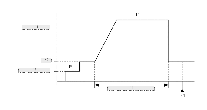
| *1 | 24 km/h (15 mph) |
| *2 | Idling |
| *3 | Ignition Switch ON |
| *4 | Total of 30 seconds or more |
-
Connect the GTS to the DLC3.
-
Turn the ignition switch to ON.
-
Turn the GTS on.
-
Clear the DTCs (even if no DTCs are stored, perform the clear DTC procedure).
-
Turn the ignition switch off and wait for at least 30 seconds.
-
Turn the ignition switch to ON [A].
-
Turn the GTS on.
-
Start the engine.
-
Drive the vehicle at 24 km/h (15 mph) or more for a total of 30 seconds or more [B].
CAUTION:
When performing the confirmation driving pattern, obey all speed limits and traffic laws.
-
Stop the vehicle.
-
Enter the following menus: Powertrain / Engine and ECT / Trouble Codes [C].
-
Read the pending DTCs.
Tech Tips
-
If a pending DTC is output, the system is malfunctioning.
-
If a pending DTC is not output, perform the following procedure.
-
-
Enter the following menus: Powertrain / Engine and ECT / Utility / All Readiness.
-
Input the DTC: P0500.
-
Check the DTC judgment result.
GTS Display Description NORMAL
-
DTC judgment completed
-
System normal
ABNORMAL
-
DTC judgment completed
-
System abnormal
INCOMPLETE
-
DTC judgment not completed
-
Perform driving pattern after confirming DTC enabling conditions
N/A
-
Unable to perform DTC judgment
-
Number of DTCs which do not fulfill DTC preconditions has reached ECU memory limit
Tech Tips
-
If the judgment result shows NORMAL, the system is normal.
-
If the judgment result shows ABNORMAL, the system has a malfunction.
-
If the judgment result shows INCOMPLETE or N/A, perform the Confirmation Driving Pattern and check the DTC judgment result again.
-
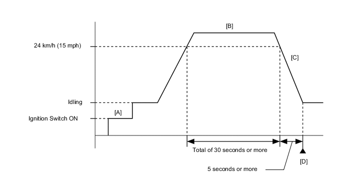
Figure 2. for Manual Transaxle:
-
Connect the GTS to the DLC3.
-
Turn the ignition switch to ON.
-
Turn the GTS on.
-
Clear the DTCs (even if no DTCs are stored, perform the clear DTC procedure).
-
Turn the ignition switch off and wait for at least 30 seconds.
-
Start the engine.
-
Turn the GTS on [A].
-
Drive the vehicle at 24 km/h (15 mph) or more for a total of 30 seconds or more [B].
CAUTION:
When performing the confirmation driving pattern, obey all speed limits and traffic laws.
-
Decelerate the vehicle by releasing the accelerator pedal for 5 seconds or more to perform the fuel cut [C].
-
Stop the vehicle.
-
Enter the following menus: Powertrain / Engine / Trouble Codes [D].
-
Read the pending DTCs.
Tech Tips
-
If a pending DTC is output, the system is malfunctioning.
-
If a pending DTC is not output, perform the following procedure.
-
-
Enter the following menus: Powertrain / Engine / Utility / All Readiness.
-
Input the DTC: P0500.
-
Check the DTC judgment result.
GTS Display Description NORMAL
-
DTC judgment completed
-
System normal
ABNORMAL
-
DTC judgment completed
-
System abnormal
INCOMPLETE
-
DTC judgment not completed
-
Perform driving pattern after confirming DTC enabling conditions
N/A
-
Unable to perform DTC judgment
-
Number of DTCs which do not fulfill DTC preconditions has reached ECU memory limit
Tech Tips
-
If the judgment result shows NORMAL, the system is normal.
-
If the judgment result shows ABNORMAL, the system has a malfunction.
-
If the judgment result shows INCOMPLETE or N/A, perform the Confirmation Driving Pattern and check the DTC judgment result again.
-
WIRING DIAGRAM
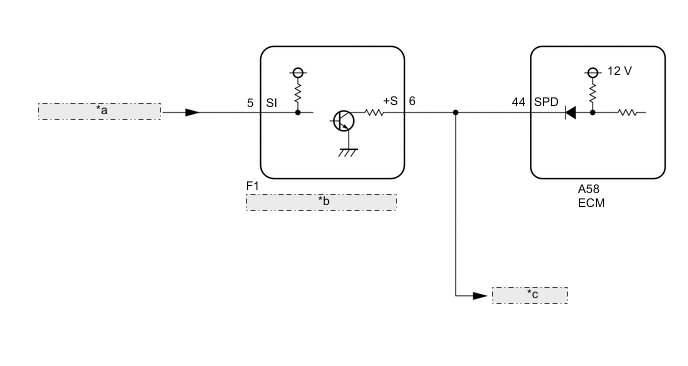
| *a | from Brake Actuator Assembly |
| *b | Combination Meter Assembly |
| *c | to Other ECUs |
CAUTION / NOTICE / HINT
Tech Tips
Read freeze frame data using the GTS. The ECM records vehicle and driving condition information as freeze frame data the moment a DTC is stored. When troubleshooting, freeze frame data can help determine if the vehicle was moving or stationary, if the engine was warmed up or not, if the air fuel ratio was lean or rich, and other data from the time the malfunction occurred.
PROCEDURE
-
READ VALUE USING GTS (VEHICLE SPEED)
-
Connect the GTS to the DLC3.
-
Turn the ignition switch to ON.
-
Turn the GTS on.
-
Enter the following menus: Powertrain / Engine and ECT / Data List / Vehicle Speed.
-
Drive the vehicle.
CAUTION:
When performing the confirmation driving pattern, obey all speed limits and traffic laws.
-
Read the value displayed on the GTS.
Result Result Proceed to Values displayed on GTS and speedometer display not equal A Values displayed on GTS and speedometer display equal B
B 
CHECK FOR INTERMITTENT PROBLEMS Click here
A 
-
-
CHECK COMBINATION METER SYSTEM (SPEED SIGNAL CIRCUIT)
-
Check the circuits that send vehicle speed signals to this system in the combination meter system.
Result Proceed to NEXT
NEXT
-
-
CONFIRM WHETHER MALFUNCTION HAS BEEN SUCCESSFULLY REPAIRED
-
Connect the GTS to the DLC3.
-
Turn the ignition switch to ON.
-
Turn the GTS on.
-
Clear the DTCs.
-
Turn the ignition switch off and wait for at least 30 seconds.
-
Start the engine.
-
Turn the GTS on.
-
Drive the vehicle in accordance with the driving pattern described in the Confirmation Driving Pattern.
-
Enter the following menus: Powertrain / Engine and ECT / Trouble Codes.
Tech Tips
If no DTCs (no pending DTCs) are output to the GTS, the repair has been successfully completed.
Result Proceed to NEXT
NEXT
END
-