SFI SYSTEM, Diagnostic DTC:C1263, C1264
| DTC Code | DTC Name |
|---|---|
| C1263 | Ejector VSV Malfunction (High) |
| C1264 | Ejector VSV Malfunction (Low) |
DESCRIPTION
Tech Tips
This DTC is applicable to CVT models only.
The brake ejector VSV is installed on the throttle by-pass and controlled by the ECM to optimally apply vacuum to the brake booster assembly.
| DTC No. | Detection Item | DTC Detection Condition | Trouble Area | MIL | Memory |
|---|---|---|---|---|---|
| C1263 | Ejector VSV Malfunction (High) |
|
|
Does not come on | DTC stored (for CVT) / - (for Manual Transaxle) |
| C1264 | Ejector VSV Malfunction (Low) |
|
|
Does not come on | DTC stored (for CVT) / - (for Manual Transaxle) |
MONITOR DESCRIPTION
The ECM monitors the terminal voltage input from the brake ejector VSV. If the voltage and brake ejector VSV operation command signal do not match, the ECM judges that there is a malfunction in the brake ejector VSV circuit and stores a DTC.
MONITOR STRATEGY
| Required Sensors/Components | Brake ejector VSV |
| Frequency of Operation | Continuous |
CONFIRMATION DRIVING PATTERN
-
Connect the GTS to the DLC3.
-
Turn the ignition switch to ON.
-
Turn the GTS on.
-
Clear the DTCs (even if no DTCs are stored, perform the clear DTC procedure).
-
Turn the ignition switch off and wait for at least 30 seconds.
-
Turn the ignition switch to ON.
-
Turn the GTS on.
-
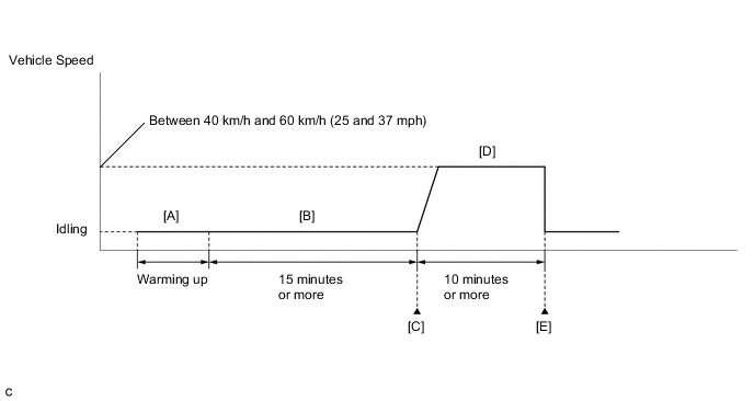
Start the engine and warm it up until the engine coolant temperature is 75°C (167°F) or higher [A].
Tech Tips
The A/C switch and all accessory switches should be off.
-
Idle the engine for 15 minutes or more [B].
-
Enter the following menus: Powertrain / Engine and ECT / Trouble Codes [C].
-
Read the pending DTCs.
Tech Tips
-
If a pending DTC is output, the system is malfunctioning.
-
If a pending DTC is not output, perform the following procedure.
-
-
Enter the following menus: Powertrain / Engine and ECT / Utility / All Readiness.
-
Input the DTC: C1263 or C1264.
-
Check the DTC judgment result.
GTS Display Description NORMAL
-
DTC judgment completed
-
System normal
ABNORMAL
-
DTC judgment completed
-
System abnormal
INCOMPLETE
-
DTC judgment not completed
-
Perform driving pattern after confirming DTC enabling conditions
N/A
-
Unable to perform DTC judgment
-
Number of DTCs which do not fulfill DTC preconditions has reached ECU memory limit
Tech Tips
-
If the judgment result shows NORMAL, the system is normal.
-
If the judgment result shows ABNORMAL, the system has a malfunction.
-
If the judgment result shows INCOMPLETE or N/A, perform steps [D] and [E].
-
-
Drive the vehicle at a constant speed between 40 and 60 km/h (25 and 37 mph) for 10 minutes or more [D].
CAUTION:
When performing the confirmation driving pattern, obey all speed limits and traffic laws.
-
Check the DTC judgment result again [E].
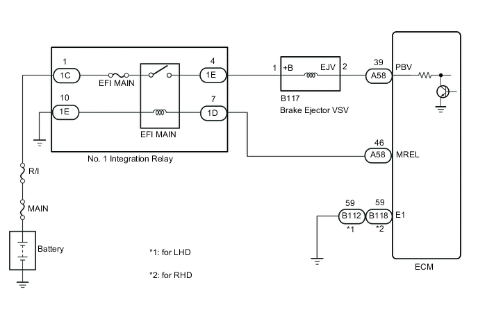
WIRING DIAGRAM
CAUTION / NOTICE / HINT
Note
Inspect the fuses for circuits related to this system before performing the following procedure.
Tech Tips
Read freeze frame data using the GTS. The ECM records vehicle and driving condition information as freeze frame data the moment a DTC is stored. When troubleshooting, freeze frame data can help determine if the vehicle was moving or stationary, if the engine was warmed up or not, if the air fuel ratio was lean or rich, and other data from the time the malfunction occurred.
PROCEDURE
-
PERFORM ACTIVE TEST USING GTS (BRAKE EJECTOR VSV INSPECTION)
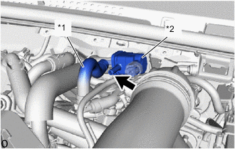
*1 No. 1 air hose (air cleaner side) *2 Brake ejector VSV
-
Disconnect the No. 1 air hose (air cleaner side) of the brake ejector VSV.
-
Connect the GTS to the DLC3.
-
Start the engine.
-
Turn the GTS on.
-
Enter the following menus: Powertrain / Engine and ECT / Active Test / Brake Ejector VSV Inspection.
-
When the brake ejector VSV is operated using the GTS, check whether the port of the brake ejector VSV applies suction your finger.
OK GTS Operation Specified Condition ON Brake ejector VSV port applies suction to finger OFF Brake ejector VSV port applies no suction to finger Result Proceed to OK NG
OK 
CHECK FOR INTERMITTENT PROBLEMS Click here
NG 
-
-
INSPECT BRAKE EJECTOR VSV
-
Inspect the brake ejector VSV.
Result Proceed to OK NG
NG
REPLACE BRAKE EJECTOR VSV Click here
OK
-
-
CHECK TERMINAL VOLTAGE (POWER SOURCE OF BRAKE EJECTOR VSV)
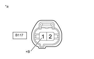
*a Front view of wire harness connector
(to Brake Ejector VSV)
-
Disconnect the brake ejector VSV connector.
-
Turn the ignition switch to ON.
-
Measure the voltage according to the value(s) in the table below.
Standard Voltage Tester Connection Switch Condition Specified Condition B117-1 (+B) - Body ground Ignition switch ON 11 to 14 V Result Proceed to OK NG
NG 
CHECK HARNESS AND CONNECTOR (BRAKE EJECTOR VSV - NO. 1 INTEGRATION RELAY) Click here
OK
-
-
CHECK HARNESS AND CONNECTOR (BRAKE EJECTOR VSV - ECM)
-
Disconnect the B117 brake ejector VSV connector.
-
Disconnect the A58 ECM connector.
-
Measure the resistance according to the value(s) in the table below.
Standard Resistance Tester Connection Condition Specified Condition A58-39 (PBV) - B117-2 (EJV) Always Below 1 Ω A58-39 (PBV) or B117-2 (EJV) - Body ground and other terminals Always 10 kΩ or higher Result Proceed to OK NG
OK
REPLACE ECM Click here
NG
REPAIR OR REPLACE HARNESS OR CONNECTOR
-
-
CHECK HARNESS AND CONNECTOR (BRAKE EJECTOR VSV - NO. 1 INTEGRATION RELAY)
-
Disconnect the B117 brake ejector VSV connector.
-
Disconnect the No. 1 integration relay connector.
-
Measure the resistance according to the value(s) in the table below.
Standard Resistance Tester Connection Condition Specified Condition B117-1 (+B) - 1E-4 Always Below 1 Ω B117-1 (+B) or 1E-4 - Body ground and other terminals Always 10 kΩ or higher Result Proceed to OK NG
OK
REPLACE NO. 1 INTEGRATION RELAY Click here
NG
REPAIR OR REPLACE HARNESS OR CONNECTOR
-