SFI SYSTEM TERMINALS OF ECM
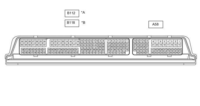
| *A | for LHD | *B | for RHD |
Tech Tips
The standard voltage, resistance and waveform between each pair of the ECM terminals is shown in the table below. The appropriate conditions for checking each pair of the terminals is also indicated. The result of checks should be compared with the standard voltage, resistance and waveform for each pair of the terminals as displayed in the Specified Condition column. The illustration above can be used as a reference to identify the ECM terminal locations.
| Terminal No. (Symbol) | Wiring Color | Terminal Description | Condition | Specified Condition |
|---|---|---|---|---|
| A58-1 (BATT) - B112-59 (E1) | Y - W-B | Battery (for measuring battery voltage and for ECM memory) | Always | 11 to 14 V |
| A58-2 (+B) - B112-59 (E1) | B - W-B | Power source of ECM | Ignition switch ON | 11 to 14 V |
| A58-3 (+B2) - B112-59 (E1) | B - W-B | Power source of ECM | Ignition switch ON | 11 to 14 V |
| A58-5 (ELS1) - B112-59 (E1) | G - W-B | Electric load signal | Taillight switch on | 11 to 14 V |
| Taillight switch off | Below 1.5 V | |||
| A58-6 (IGSW) - B112-59 (E1) | R - W-B | Ignition switch signal | Ignition switch ON | 11 to 14 V |
| A58-7 (FANL) - B112-59 (E1) | R - W-B | Cooling fan relay | Ignition switch ON (cooling fan not operated) | 11 to 14 V |
| Idling with A/C on, or high engine coolant temperature (cooling fan operated) | Below 1.5 V | |||
| A58-8 (FANH) - B112-59 (E1) | G - W-B | No. 2 cooling fan relay | Ignition switch ON (cooling fan not operated) | 11 to 14 V |
| Idling with high engine coolant temperature (cooling fan operated at high speed) | Below 1.5 V | |||
| A58-9 (STP) - B112-59 (E1) | LG - W-B | Stop light switch assembly signal | Brake pedal depressed | 7.5 to 14 V |
| Brake pedal released | Below 1.5 V | |||
| A58-10 (ST1-) - B112-59 (E1) | Y - W-B | Stop light switch assembly signal (opposite of voltage at STP terminal) |
Ignition switch ON, brake pedal depressed | Below 1.5 V |
| Ignition switch ON, brake pedal released | 7.5 to 14 V | |||
| A58-13 (CANH) - B112-59 (E1) | L - W-B | CAN communication line | Ignition switch ON | Pulse generation (See waveform 1) |
| A58-18 (INH) - B112-59 (E1) | L - W-B | Wiper switch signal | Front wiper motor in HI operation | 11 to 14 V |
| Front wiper motor off | Below 1.5 V | |||
| A58-23 (NSW) - B112-59 (E1) | BE - W-B | Park/Neutral position switch signal*4 | Ignition switch ON, shift lever in P or N (neutral) | Below 3.0 V |
| Ignition switch ON, shift lever not in P or N (neutral) | 11 to 14 V | |||
| Clutch start switch signal*5 | Ignition switch ON, clutch pedal fully released | 11 to 14 V | ||
| Ignition switch ON, clutch pedal fully depressed | Below 1.5 V | |||
| A58-26 (CANL) - B112-59 (E1) | W - W-B | CAN communication line | Ignition switch ON | Pulse generation (See waveform 2) |
| A58-27 (W) - B112-59 (E1) | B - W-B | MIL | Ignition switch ON (MIL goes off) | Below 1.5 V |
| Idling | 11 to 14 V | |||
| A58-28 (IMI) - B112-59 (E1) | G - W-B | ID code box (immobiliser code ECU) communication input | Ignition switch off | 11 to 14 V |
| A58-29 (STA) - B112-59 (E1) | L - W-B*4 BR - W-B*5 |
Starter assembly signal | Cranking | 5.5 V or higher |
| A58-30 (NEO)*1 - B112-59 (E1) | V - W-B | Engine speed signal sent to other ECUs | Idling with warm engine | Pulse generation (See waveform 3) |
| A58-31 (TACH) - B112-59 (E1) | LG - W-B | Engine speed signal | Idling with warm engine | Pulse generation (See waveform 4) |
| A58-32 (EC) - Body ground | W-B - Body ground | Earth (ground) circuit of ECM | Always | Below 1 Ω |
| A58-33 (TC) - B112-59 (E1) | L - W-B | Terminal TC of DLC3 | Ignition switch ON | 11 to 14 V |
| A58-34 (ELS2) - B112-59 (E1) | B - W-B | Electric load signal | Defogger switch on | 11 to 14 V |
| Defogger switch off | Below 1.5 V | |||
| A58-39 (PBV) - B112-59 (E1) | L - W-B | Brake ejector VSV operation signal | Ignition switch ON | 11 to 14 V |
| A58-40 (PB) - A58-54 (EPB) | LG - R | Vacuum sensor signal | Idling with warm engine, brake pedal released | 1.5 to 2.0 V |
| A58-41 (FPC) - B112-59 (E1) | L - W-B | Fuel pump control | Engine stopped and ignition switch ON (fuel pump not operate) | 11 to 14 V |
| Engine stopped and ignition switch ON (fuel pump operate) | Below 1.5 V | |||
| A58-44 (SPD) - B112-59 (E1) | V - W-B | Vehicle speed signal from combination meter assembly signal | Driving at 20 km/h (12 mph) | Pulse generation (See waveform 5) |
| A58-45 (IMO) - B112-59 (E1) | W - W-B | ID code box (immobiliser code ECU) communication output | Ignition switch off | 11 to 14 V |
| A58-46 (MREL) - B112-59 (E1) | GR - W-B | EFI MAIN relay operation signal | Ignition switch ON | 11 to 14 V |
| A58-47 (VPA) - A58-48 (EPA) | R - V | Accelerator pedal position sensor signal (for engine control) | Ignition switch ON, accelerator pedal fully released | 0.5 to 1.1 V |
| Ignition switch ON, accelerator pedal fully depressed | 2.6 to 4.5 V | |||
| A58-49 (VCPA) - A58-48 (EPA) | G - V | Power source of accelerator pedal position sensor (for VPA) | Ignition switch ON | 4.5 to 5.5 V |
| A58-50 (VPA2) - A58-51 (EPA2) | L - B | Accelerator pedal position sensor signal | Ignition switch ON, accelerator pedal fully released | 1.2 to 2.0 V |
| Ignition switch ON, accelerator pedal fully depressed | 3.4 to 4.75 V | |||
| A58-52 (VCP2) - A58-51 (EPA2) | W - B | Power source of accelerator pedal position sensor (for VPA2) | Ignition switch ON | 4.5 to 5.5 V |
| A58-55 (VCPB) - A58-54 (EPB) | G - R | Power source of vacuum sensor (for PB) | Ignition switch ON | 4.75 to 5.25 V |
| B112-26 (E04) - Body ground | W-B - Body ground | Earth (ground) circuit of ECM | Always | Below 1 Ω |
| B112-27 (HA1A) - B112-26 (E04) | G - W-B | Air fuel ratio sensor heater operation signal | Idling with cold engine | Pulse generation (See waveform 6) |
| Ignition switch ON | 11 to 14 V | |||
| B112-28 (ME01) - Body ground | BR - Body ground | Earth (ground) circuit of ECM | Always | Below 1 Ω |
| B112-29 (+BM) - B112-59 (E1) | GR - W-B | Power source of throttle actuator | Always | 11 to 14 V |
| B112-30 (M-) - B112-28 (ME01) | BR - BR | Throttle actuator operation signal (negative terminal) | Idling with warm engine | Pulse generation (See waveform 7) |
| B112-33 (PRG) - B112-59 (E1) | L - W-B | Purge VSV operation signal | Ignition switch ON | 11 to 14 V |
| Idling, under purge control | Pulse generation (See waveform 8) |
|||
| B112-35 (EDT1) - B112-59 (E1) | G - W-B | Cam timing control motor signal | Idling with warm engine | Pulse generation (See waveform 9) |
| B112-37 (OE1+) - B112-36 (OE1-) | L - P | Camshaft timing oil control valve assembly operation signal | Idling with warm engine | Pulse generation (See waveform 10) |
| B112-56 (HT1B) - B112-59 (E1) | L - W-B | Heated oxygen sensor heater operation signal | Idling | Below 3.0 V |
| Ignition switch ON | 11 to 14 V | |||
| B112-57 (E01) - Body ground | BR - Body ground | Earth (ground) circuit of ECM | Always | Below 1 Ω |
| B112-58 (E02) - Body ground | BR - Body ground | Earth (ground) circuit of ECM | Always | Below 1 Ω |
| B112-59 (E1) - Body ground | W-B - Body ground | Earth (ground) circuit of ECM | Always | Below 1 Ω |
| B112-60 (M+) - B112-28 (ME01) | G - BR | Throttle actuator operation signal (positive terminal) | Idling with warm engine | Pulse generation (See waveform 11) |
| B112-66 (EMF1) - B112-59 (E1) | W - W-B | Cam timing control motor signal | Idling with warm engine | 0.3 to 1.3 V |
| B112-71 (EMR1) - B112-59 (E1) | GR - W-B | Cam timing control motor signal | Idling with warm engine | Pulse generation (See waveform 12) |
| B112-72 (IGT4) - B112-59 (E1) | LG - W-B | No. 1 ignition coil (No. 4 cylinder) signal (ignition signal) | Idling with warm engine | Pulse generation (See waveform 13) |
| B112-73 (IGT3) - B112-59 (E1) | G - W-B | No. 1 ignition coil (No. 3 cylinder) signal (ignition signal) | Idling with warm engine | Pulse generation (See waveform 13) |
| B112-74 (IGT2) - B112-59 (E1) | V - W-B | No. 1 ignition coil (No. 2 cylinder) signal (ignition signal) | Idling with warm engine | Pulse generation (See waveform 13) |
| B112-75 (IGT1) - B112-59 (E1) | W - W-B | No. 1 ignition coil (No. 1 cylinder) signal (ignition signal) | Idling with warm engine | Pulse generation (See waveform 13) |
| B112-77 (VCPM) - B112-76 (EPIM) | Y - LG | Power source of vacuum sensor (manifold absolute pressure sensor) | Ignition switch ON | 4.5 to 5.5 V |
| B112-78 (PIM) - B112-76 (EPIM) | B - LG | Vacuum sensor (manifold absolute pressure sensor) signal | Idling with warm engine | 1.2 to 2.0 V |
| B112-79 (PTO) - B112-109 (EPTO)*4 | L - BE | Oil pressure sensor signal | Engine idling with shift lever in P or N (neutral) | 0.8 to 1.2 V |
| B112-80 (VV1+) - B112-112 (VV1-) | V - P | Camshaft position sensor (for intake camshaft) signal | Idling with warm engine | Pulse generation (See waveform 14) |
| B112-81 (VCNE) - B112-113 (NE-) | B - Y | Power source of crankshaft position sensor | Ignition switch ON | 4.5 to 5.5 V |
| B112-82 (EV1+) - B112-115 (EV1-) | GR - W | Camshaft position sensor (for exhaust camshaft) signal | Idling with warm engine | Pulse generation (See waveform 14) |
| B112-84 (VHAC) - B112-83 (EHAC)*3 | V - G | Atmospheric pressure sensor power supply |
|
4.5 to 5.5 V |
| B112-85 (HAC) - B112-83 (EHAC)*3 | L - G | Atmospheric pressure sensor signal |
|
1.6 to 2.0 V |
|
2.2 to 2.6 V | |||
|
3.4 to 3.8 V | |||
| B112-86(IB) - B112-118 (EIB) *3 | L - V | Battery state sensor assembly | Ignition switch ON | 0.2 to 4.8 V |
| B112-87(THB) - B112-118 (EIB) *3 | SB - V | Battery temperature sensor (built into battery state sensor assembly) | Ignition switch off | 0.2 to 4.8 V |
| B112-110 (VCPT) - B112-109 (EPTO)*4 | V - BE | Power supply for oil pressure sensor | Ignition switch ON | 4.75 to 5.25 V |
| B112-117 (VCIB) - B112-118 (EIB)*3 | P - V | Power source of battery state sensor assembly | Ignition switch ON | 4.5 to 5.5 V |
| B112-94 (EMD1) - B112-59 (E1) | V - W-B | Cam timing control motor signal | Idling with warm engine | Pulse generation (See waveform 15) |
| B112-95 (#20) - B112-57 (E01) | GR - BR | Fuel injector assembly (No. 2 cylinder) | Ignition switch ON | 11 to 14 V |
| Idling with warm engine | Pulse generation (See waveform 16) |
|||
| B112-96 (#30) - B112-57 (E01) | P - BR | Fuel injector assembly (No. 3 cylinder) | Ignition switch ON | 11 to 14 V |
| Idling with warm engine | Pulse generation (See waveform 16) |
|||
| B112-97 (#40) - B112-57 (E01) | L - BR | Fuel injector assembly (No. 4 cylinder) | Ignition switch ON | 11 to 14 V |
| Idling with warm engine | Pulse generation (See waveform 16) |
|||
| B112-98 (#10) - B112-57 (E01) | B - BR | Fuel injector assembly (No. 1 cylinder) | Ignition switch ON | 11 to 14 V |
| Idling with warm engine | Pulse generation (See waveform 16) |
|||
| B112-99 (OX1B) - B112-131 (EX1B) | W - R | Heated oxygen sensor signal | Engine speed maintained at 2500 rpm for 2 minutes after warming up engine | Pulse generation (See waveform 17) |
| B112-100 (A1A+) - B112-59 (E1) | R - W-B | Air fuel ratio sensor signal | Ignition switch ON | 3.0 to 3.6 V |
| B112-101 (VTA2) - B112-133 (ETA) | GR - V | Throttle position sensor signal (for sensor malfunction detection) | Ignition switch ON, accelerator pedal fully released | 2.1 to 3.1 V |
| Ignition switch ON, accelerator pedal fully depressed | 4.6 to 5.0 V | |||
| B112-105 (EGR4) - B112-59 (E1) | Y - W-B | EGR valve operation signal | Engine racing with warm engine | Pulse generation (See waveform 18) |
| B112-106 (EGR2) - B112-59 (E1) | LG - W-B | EGR valve operation signal | Engine racing with warm engine | Pulse generation (See waveform 18) |
| B112-107 (EGR3) - B112-59 (E1) | W - W-B | EGR valve operation signal | Engine racing with warm engine | Pulse generation (See waveform 19) |
| B112-108 (GE01) - Body ground | BR - Body ground | Shielded earth (ground) circuit of throttle actuator | Always | Below 1 Ω |
| B112-111 (VCV1) - B112-112 (VV1-) | R - P | Power source of camshaft position sensor (for intake camshaft) (specific voltage) | Ignition switch ON | 4.5 to 5.5 V |
| B112-114 (NE+) - B112-113 (NE-) | P - Y | Crankshaft position sensor signal | Idling with warm engine | Pulse generation (See waveform 20) |
| B112-116 (VCE1) - B112-115 (EV1-) | L - W | Power source of camshaft position sensor (for exhaust camshaft) (specific voltage) | Ignition switch ON | 4.5 to 5.5 V |
| B112-120 (THW) - B112-119 (ETHW) | V - BR | Engine coolant temperature sensor signal | Idling, engine coolant temperature 80°C (176°F) | 0.2 to 1.0 V |
| B112-122 (KNK1) - B112-121 (EKNK) | R - G | Knock sensor signal | Engine speed maintained at 4000 rpm after warming up engine | Pulse generation (See waveform 21) |
| B112-132 (A1A-) - B112-59 (E1) | G - W-B | Air fuel ratio sensor signal | Ignition switch ON | 2.7 to 3.3 V |
| B112-134 (VCTA) - B112-133 (ETA) | W - V | Power source of throttle position sensor (specific voltage) | Ignition switch ON | 4.5 to 5.5 V |
| B112-135 (VTA1) - B112-133 (ETA) | Y - V | Throttle position sensor signal (for engine control) | Ignition switch ON, accelerator pedal fully released | 0.5 to 1.1 V |
| Ignition switch ON, accelerator pedal fully depressed | 3.2 to 4.8 V | |||
| B112-137 (VG) - B112-104 (E2G) | GR - L | Mass air flow meter signal | Idling, shift lever in P or N (neutral), A/C switch off | 0.5 to 3.0 V |
| B112-138 (THA) - B112-139 (ETHA) | P - G | Intake air temperature sensor signal | Idling, intake air temperature 20°C (68°F) | 0.5 to 3.4 V |
| B112-140 (EGR1) - B112-59 (E1) | R - W-B | EGR valve operation signal | Engine racing with warm engine | Pulse generation (See waveform 19) |
| Terminal No. (Symbol) | Wiring Color | Terminal Description | Condition | Specified Condition |
|---|---|---|---|---|
| A58-1 (BATT) - B118-59 (E1) | Y - W-B | Battery (for measuring battery voltage and for ECM memory) | Always | 11 to 14 V |
| A58-2 (+B) - B118-59 (E1) | B - W-B | Power source of ECM | Ignition switch ON | 11 to 14 V |
| A58-3 (+B2) - B118-59 (E1) | B - W-B | Power source of ECM | Ignition switch ON | 11 to 14 V |
| A58-5 (ELS1) - B118-59 (E1) | G - W-B | Electric load signal | Taillight switch on | 11 to 14 V |
| Taillight switch off | Below 1.5 V | |||
| A58-6 (IGSW) - B118-59 (E1) | R - W-B | Ignition switch signal | Ignition switch ON | 11 to 14 V |
| A58-7 (FANL) - B118-59 (E1) | R - W-B | Cooling fan relay | Ignition switch ON (cooling fan not operated) | 11 to 14 V |
| Idling with A/C on, or high engine coolant temperature (cooling fan operated) | Below 1.5 V | |||
| A58-8 (FANH) - B118-59 (E1) | G - W-B | No. 2 cooling fan relay | Ignition switch ON (cooling fan not operated) | 11 to 14 V |
| Idling with high engine coolant temperature (cooling fan operated at high speed) | Below 1.5 V | |||
| A58-9 (STP) - B118-59 (E1) | LG - W-B | Stop light switch assembly signal | Brake pedal depressed | 7.5 to 14 V |
| Brake pedal released | Below 1.5 V | |||
| A58-10 (ST1-) - B118-59 (E1) | Y - W-B | Stop light switch assembly signal (opposite of voltage at STP terminal) |
Ignition switch ON, brake pedal depressed | Below 1.5 V |
| Ignition switch ON, brake pedal released | 7.5 to 14 V | |||
| A58-13 (CANH) - B118-59 (E1) | L - W-B | CAN communication line | Ignition switch ON | Pulse generation (See waveform 1) |
| A58-18 (INH) - B118-59 (E1) | L - W-B | Wiper switch signal | Front wiper motor in HI operation | 11 to 14 V |
| Front wiper motor off | Below 1.5 V | |||
| A58-23 (NSW) - B118-59 (E1) | BE - W-B | Park/Neutral position switch signal*4 | Ignition switch ON, shift lever in P or N (neutral) | Below 3.0 V |
| Ignition switch ON, shift lever not in P or N (neutral) | 11 to 14 V | |||
| Clutch start switch signal*5 | Ignition switch ON, clutch pedal fully released | 11 to 14 V | ||
| Ignition switch ON, clutch pedal fully depressed | Below 1.5 V | |||
| A58-26 (CANL) - B118-59 (E1) | W - W-B | CAN communication line | Ignition switch ON | Pulse generation (See waveform 2) |
| A58-27 (W) - B118-59 (E1) | B - W-B | MIL | Ignition switch ON (MIL goes off) | Below 1.5 V |
| Idling | 11 to 14 V | |||
| A58-28 (IMI) - B118-59 (E1) | G - W-B | ID code box (immobiliser code ECU) communication input | Ignition switch off | 11 to 14 V |
| A58-29 (STA) - B118-59 (E1) | L - W-B*4 BR - W-B*5 |
Starter assembly signal | Cranking | 5.5 V or higher |
| A58-30 (NEO)*1 - B118-59 (E1) | V - W-B | Engine speed signal sent to other ECUs | Idling with warm engine | Pulse generation (See waveform 3) |
| A58-31 (TACH) - B118-59 (E1) | LG - W-B | Engine speed signal | Idling with warm engine | Pulse generation (See waveform 4) |
| A58-32 (EC) - Body ground | W-B - Body ground | Earth (ground) circuit of ECM | Always | Below 1 Ω |
| A58-33 (TC) - B118-59 (E1) | L - W-B | Terminal TC of DLC3 | Ignition switch ON | 11 to 14 V |
| A58-34 (ELS2) - B118-59 (E1) | B - W-B | Electric load signal | Defogger switch on | 11 to 14 V |
| Defogger switch off | Below 1.5 V | |||
| A58-39 (PBV) - B118-59 (E1) | L - W-B | Brake ejector VSV operation signal | Ignition switch ON | 11 to 14 V |
| A58-40 (PB) - A58-54 (EPB) | LG - R | Vacuum sensor signal | Idling with warm engine, brake pedal released | 1.5 to 2.0 V |
| A58-41 (FPC) - B118-59 (E1) | L - W-B | Fuel pump control | Engine stopped and ignition switch ON (fuel pump not operate) | 11 to 14 V |
| Engine stopped and ignition switch ON (fuel pump operate) | Below 1.5 V | |||
| A58-44 (SPD) - B118-59 (E1) | V - W-B | Vehicle speed signal from combination meter assembly signal | Driving at 20 km/h (12 mph) | Pulse generation (See waveform 5) |
| A58-45 (IMO) - B118-59 (E1) | W - W-B | ID code box (immobiliser code ECU) communication output | Ignition switch off | 11 to 14 V |
| A58-46 (MREL) - B118-59 (E1) | GR - W-B | EFI MAIN relay operation signal | Ignition switch ON | 11 to 14 V |
| A58-47 (VPA) - A58-48 (EPA) | R - V | Accelerator pedal position sensor signal (for engine control) | Ignition switch ON, accelerator pedal fully released | 0.5 to 1.1 V |
| Ignition switch ON, accelerator pedal fully depressed | 2.6 to 4.5 V | |||
| A58-49 (VCPA) - A58-48 (EPA) | G - V | Power source of accelerator pedal position sensor (for VPA) | Ignition switch ON | 4.5 to 5.5 V |
| A58-50 (VPA2) - A58-51 (EPA2) | L - B | Accelerator pedal position sensor signal | Ignition switch ON, accelerator pedal fully released | 1.2 to 2.0 V |
| Ignition switch ON, accelerator pedal fully depressed | 3.4 to 4.75 V | |||
| A58-52 (VCP2) - A58-51 (EPA2) | W - B | Power source of accelerator pedal position sensor (for VPA2) | Ignition switch ON | 4.5 to 5.5 V |
| A58-55 (VCPB) - A58-54 (EPB) | G - R | Power source of vacuum sensor (for PB) | Ignition switch ON | 4.75 to 5.25 V |
| B118-26 (E04) - Body ground | W-B - Body ground | Earth (ground) circuit of ECM | Always | Below 1 Ω |
| B118-27 (HA1A) - B118-26 (E04) | G - W-B | Air fuel ratio sensor heater operation signal | Idling with cold engine | Pulse generation (See waveform 6) |
| Ignition switch ON | 11 to 14 V | |||
| B118-28 (ME01) - Body ground | BR - Body ground | Earth (ground) circuit of ECM | Always | Below 1 Ω |
| B118-29 (+BM) - B118-59 (E1) | GR - W-B | Power source of throttle actuator | Always | 11 to 14 V |
| B118-30 (M-) - B118-28 (ME01) | BR - BR | Throttle actuator operation signal (negative terminal) | Idling with warm engine | Pulse generation (See waveform 7) |
| B118-33 (PRG) - B118-59 (E1) | L - W-B | Purge VSV operation signal | Ignition switch ON | 11 to 14 V |
| Idling, under purge control | Pulse generation (See waveform 8) |
|||
| B118-35 (EDT1) - B118-59 (E1) | G - W-B | Cam timing control motor signal | Idling with warm engine | Pulse generation (See waveform 9) |
| B118-37 (OE1+) - B118-36 (OE1-) | L - P | Camshaft timing oil control valve assembly operation signal | Idling with warm engine | Pulse generation (See waveform 10) |
| B118-56 (HT1B) - B118-59 (E1) | L - W-B | Heated oxygen sensor heater operation signal | Idling | Below 3.0 V |
| Ignition switch ON | 11 to 14 V | |||
| B118-57 (E01) - Body ground | BR - Body ground | Earth (ground) circuit of ECM | Always | Below 1 Ω |
| B118-58 (E02) - Body ground | BR - Body ground | Earth (ground) circuit of ECM | Always | Below 1 Ω |
| B118-59 (E1) - Body ground | W-B - Body ground | Earth (ground) circuit of ECM | Always | Below 1 Ω |
| B118-60 (M+) - B118-28 (ME01) | G - BR | Throttle actuator operation signal (positive terminal) | Idling with warm engine | Pulse generation (See waveform 11) |
| B118-66 (EMF1) - B118-59 (E1) | W - W-B | Cam timing control motor signal | Idling with warm engine | 0.3 to 1.3 V |
| B118-71 (EMR1) - B118-59 (E1) | GR - W-B | Cam timing control motor signal | Idling with warm engine | Pulse generation (See waveform 12) |
| B118-72 (IGT4) - B118-59 (E1) | LG - W-B | No. 1 ignition coil (No. 4 cylinder) signal (ignition signal) | Idling with warm engine | Pulse generation (See waveform 13) |
| B118-73 (IGT3) - B118-59 (E1) | G - W-B | No. 1 ignition coil (No. 3 cylinder) signal (ignition signal) | Idling with warm engine | Pulse generation (See waveform 13) |
| B118-74 (IGT2) - B118-59 (E1) | V - W-B | No. 1 ignition coil (No. 2 cylinder) signal (ignition signal) | Idling with warm engine | Pulse generation (See waveform 13) |
| B118-75 (IGT1) - B118-59 (E1) | W - W-B | No. 1 ignition coil (No. 1 cylinder) signal (ignition signal) | Idling with warm engine | Pulse generation (See waveform 13) |
| B118-77 (VCPM) - B118-76 (EPIM) | Y - LG | Power source of vacuum sensor (manifold absolute pressure sensor) | Ignition switch ON | 4.5 to 5.5 V |
| B118-78 (PIM) - B118-76 (EPIM) | B - LG | Vacuum sensor (manifold absolute pressure sensor) signal | Idling with warm engine | 1.2 to 2.0 V |
| B118-79 (PTO) - B118-109 (EPTO)*4 | L - BE | Oil pressure sensor signal | Engine idling with shift lever in P or N (neutral) | 0.8 to 1.2 V |
| B118-80 (VV1+) - B118-112 (VV1-) | V - P | Camshaft position sensor (for intake camshaft) signal | Idling with warm engine | Pulse generation (See waveform 14) |
| B118-81 (VCNE) - B118-113 (NE-) | B - Y | Power source of crankshaft position sensor | Ignition switch ON | 4.5 to 5.5 V |
| B118-82 (EV1+) - B118-115 (EV1-) | GR - W | Camshaft position sensor (for exhaust camshaft) signal | Idling with warm engine | Pulse generation (See waveform 14) |
| B118-84 (VHAC) - B118-83 (EHAC) | V - G | Atmospheric pressure sensor power supply |
|
4.5 to 5.5 V |
| B118-85 (HAC) - B118-83 (EHAC) | L - G | Atmospheric pressure sensor signal |
|
1.6 to 2.0 V |
|
2.2 to 2.6 V | |||
|
3.4 to 3.8 V | |||
| B118-86(IB) - B118-118 (EIB) | L - V | Battery current sensor assembly | Ignition switch ON | 0.2 to 4.8 V |
| B118-87(THB) - B118-118 (EIB) | SB - V | Battery temperature sensor (built into battery current sensor assembly) | Ignition switch off | 0.2 to 4.8 V |
| B118-110 (VCPT) - B118-109 (EPTO)*4 | V - BE | Power supply for oil pressure sensor | Ignition switch ON | 4.75 to 5.25 V |
| B118-117 (VCIB) - B118-118 (EIB) | P - V | Power source of battery current sensor assembly | Ignition switch ON | 4.5 to 5.5 V |
| B118-94 (EMD1) - B118-59 (E1) | V - W-B | Cam timing control motor signal | Idling with warm engine | Pulse generation (See waveform 15) |
| B118-95 (#20) - B118-57 (E01) | GR - BR | Fuel injector assembly (No. 2 cylinder) | Ignition switch ON | 11 to 14 V |
| Idling with warm engine | Pulse generation (See waveform 16) |
|||
| B118-96 (#30) - B118-57 (E01) | P - BR | Fuel injector assembly (No. 3 cylinder) | Ignition switch ON | 11 to 14 V |
| Idling with warm engine | Pulse generation (See waveform 16) |
|||
| B118-97 (#40) - B118-57 (E01) | L - BR | Fuel injector assembly (No. 4 cylinder) | Ignition switch ON | 11 to 14 V |
| Idling with warm engine | Pulse generation (See waveform 16) |
|||
| B118-98 (#10) - B118-57 (E01) | B - BR | Fuel injector assembly (No. 1 cylinder) | Ignition switch ON | 11 to 14 V |
| Idling with warm engine | Pulse generation (See waveform 16) |
|||
| B118-99 (OX1B) - B118-131 (EX1B) | W - R | Heated oxygen sensor signal | Engine speed maintained at 2500 rpm for 2 minutes after warming up engine | Pulse generation (See waveform 17) |
| B118-100 (A1A+) - B118-59 (E1) | R - W-B | Air fuel ratio sensor signal | Ignition switch ON | 3.0 to 3.6 V |
| B118-101 (VTA2) - B118-133 (ETA) | GR - V | Throttle position sensor signal (for sensor malfunction detection) | Ignition switch ON, accelerator pedal fully released | 2.1 to 3.1 V |
| Ignition switch ON, accelerator pedal fully depressed | 4.6 to 5.0 V | |||
| B118-105 (EGR4) - B118-59 (E1) | Y - W-B | EGR valve operation signal | Engine racing with warm engine | Pulse generation (See waveform 18) |
| B118-106 (EGR2) - B118-59 (E1) | LG - W-B | EGR valve operation signal | Engine racing with warm engine | Pulse generation (See waveform 18) |
| B118-107 (EGR3) - B118-59 (E1) | W - W-B | EGR valve operation signal | Engine racing with warm engine | Pulse generation (See waveform 19) |
| B118-108 (GE01) - Body ground | BR - Body ground | Shielded earth (ground) circuit of throttle actuator | Always | Below 1 Ω |
| B118-111 (VCV1) - B118-112 (VV1-) | R - P | Power source of camshaft position sensor (for intake camshaft) (specific voltage) | Ignition switch ON | 4.5 to 5.5 V |
| B118-114 (NE+) - B118-113 (NE-) | P - Y | Crankshaft position sensor signal | Idling with warm engine | Pulse generation (See waveform 20) |
| B118-116 (VCE1) - B118-115 (EV1-) | L - W | Power source of camshaft position sensor (for exhaust camshaft) (specific voltage) | Ignition switch ON | 4.5 to 5.5 V |
| B118-120 (THW) - B118-119 (ETHW) | V - BR | Engine coolant temperature sensor signal | Idling, engine coolant temperature 80°C (176°F) | 0.2 to 1.0 V |
| B118-122 (KNK1) - B118-121 (EKNK) | R - G | Knock sensor signal | Engine speed maintained at 4000 rpm after warming up engine | Pulse generation (See waveform 21) |
| B118-132 (A1A-) - B118-59 (E1) | G - W-B | Air fuel ratio sensor signal | Ignition switch ON | 2.7 to 3.3 V |
| B118-134 (VCTA) - B118-133 (ETA) | W - V | Power source of throttle position sensor (specific voltage) | Ignition switch ON | 4.5 to 5.5 V |
| B118-135 (VTA1) - B118-133 (ETA) | Y - V | Throttle position sensor signal (for engine control) | Ignition switch ON, accelerator pedal fully released | 0.5 to 1.1 V |
| Ignition switch ON, accelerator pedal fully depressed | 3.2 to 4.8 V | |||
| B118-137 (VG) - B118-104 (E2G) | GR - L | Mass air flow meter signal | Idling, shift lever in P or N (neutral), A/C switch off | 0.5 to 3.0 V |
| B118-138 (THA) - B118-139 (ETHA) | P - G | Intake air temperature sensor signal | Idling, intake air temperature 20°C (68°F) | 0.5 to 3.4 V |
| B118-140 (EGR1) - B118-59 (E1) | R - W-B | EGR valve operation signal | Engine racing with warm engine | Pulse generation (See waveform 19) |
-
*1: w/ Entry and Start System
-
*2: w/ Stop and Start System
-
*3: w/o Stop and Start System
-
*4: for CVT
-
*5: for Manual Transaxle
-
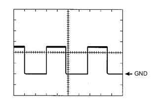
WAVEFORM 1
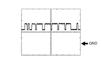
CAN Communication Signal (Reference) ECM Terminal Name Between CANH and E1 Tester Range 1 V/DIV., 10 μs./DIV. Condition Ignition switch ON Tech Tips
The waveform varies depending on the CAN communication signal.
-
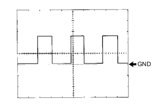
WAVEFORM 2
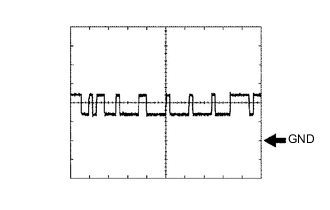
CAN Communication Signal (Reference) ECM Terminal Name Between CANL and E1 Tester Range 1 V/DIV., 10 μs./DIV. Condition Ignition switch ON Tech Tips
The waveform varies depending on the CAN communication signal.
-
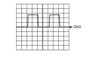
WAVEFORM 3
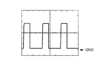
Engine Speed Signal ECM Terminal Name Between NEO and E1 Tester Range 2 V/DIV., 2 ms./DIV. Condition Idling with warm engine Tech Tips
The wavelength becomes shorter as the engine speed increases.
-
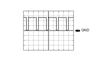
WAVEFORM 4
Engine Speed Signal ECM Terminal Name Between TACH and E1 Tester Range 5 V/DIV., 10 ms./DIV. Condition Idling with warm engine Tech Tips
The wavelength becomes shorter as the engine speed increases.
-
WAVEFORM 5
Vehicle Speed Signal ECM Terminal Name Between SPD and E1 Tester Range 5 V/DIV., 20 ms./DIV. Condition Driving at 20 km/h (12 mph) Tech Tips
The wavelength becomes shorter as the vehicle speed increases.
-
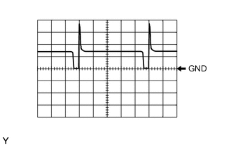
WAVEFORM 6
Air Fuel Ratio Sensor Heater Operation Signal ECM Terminal Name Between HA1A and E04 Tester Range 5 V/DIV., 10 ms./DIV. Condition Idling with cold engine -
WAVEFORM 7
Throttle Actuator Negative Terminal Signal ECM Terminal Name Between M- and ME01 Tester Range 5 V/DIV., 1 ms./DIV. Condition Idling with warm engine Tech Tips
The duty ratio varies depending on the throttle actuator operation.
-
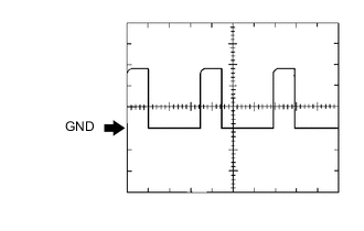
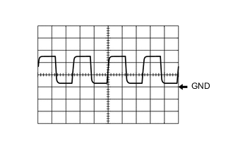
WAVEFORM 8
Purge VSV Operation Signal ECM Terminal Name Between PRG and E1 Tester Range 10 V/DIV., 20 ms./DIV. Condition Idling, under purge control Tech Tips
If the waveform is not similar to the illustration, check the waveform again after idling for 10 minutes or more.
-
WAVEFORM 9
Cam Timing Control Motor EDT Signal ECM Terminal Name Between EDT1 and E1 Tester Range 1 V/DIV., 5 ms./DIV. Condition Idling with warm engine -
WAVEFORM 10
Camshaft Timing Oil Control Valve Assembly Operation Signal ECM Terminal Name Between OE1+ and OE1- Tester Range 5 V/DIV., 1 ms./DIV. Condition Idling -
WAVEFORM 11
Throttle Actuator Positive Terminal Signal ECM Terminal Name Between M+ and ME01 Tester Range 5 V/DIV., 1 ms./DIV. Condition Idling with warm engine Tech Tips
The duty ratio varies depending on the throttle actuator operation.
-
WAVEFORM 12
Cam Timing Control Motor EMR Signal ECM Terminal Name Between EMR1 and E1 Tester Range 2 V/DIV., 5 ms./DIV. Condition Idling with warm engine Tech Tips
The wavelength becomes shorter as the engine speed increases.
-
WAVEFORM 13
Igniter IGT Signal (from ECM to Igniter) ECM Terminal Name Between IGT (1 to 4) and E1 Tester Range 2 V/DIV., 20 ms./DIV. Condition Idling with warm engine Tech Tips
The wavelength becomes shorter as the engine speed increases.
-
WAVEFORM 14
Camshaft Position Sensor Signal ECM Terminal Name CH1: Between VV1+ and VV1-
CH2: Between EV1+ and EV1-
Tester Range 5 V/DIV., 20 ms./DIV. Condition Idling with warm engine Tech Tips
The wavelength becomes shorter as the engine speed increases.
-
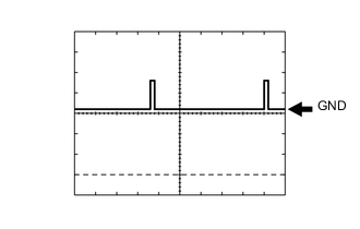
WAVEFORM 15
Cam Timing Control Motor EMD Signal ECM Terminal Name Between EMD1 and E1 Tester Range 2 V/DIV., 100 ms./DIV. Condition Idling with warm engine -
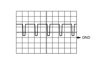
WAVEFORM 16
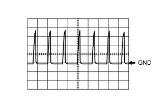
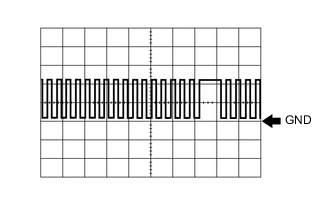
No. 1 (to No. 4) Fuel Injector Assembly Signal ECM Terminal Name Between #10 (to #40) and E01 Tester Range 20 V/DIV., 20 ms./DIV. Condition Idling with warm engine Tech Tips
The wavelength becomes shorter as the engine speed increases.
-
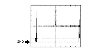
WAVEFORM 17
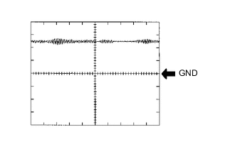
Heated Oxygen Sensor Signal ECM Terminal Name Between OX1B and EX1B Tester Range 0.2 V/DIV., 200 ms./DIV. Condition Engine speed maintained at 2500 rpm for 2 minutes after warming up engine Tech Tips
In the Data List, the item O2S B1S2 shows the values input to the ECM from the heated oxygen sensor.
-
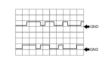
WAVEFORM 18
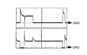
EGR Valve Assembly Operation Signal ECM Terminal Name CH1: Between EGR2 and E1
CH2: Between EGR4 and E1
Tester Range 10 V/DIV., 20 ms./DIV. Condition Engine racing with warm engine -
WAVEFORM 19
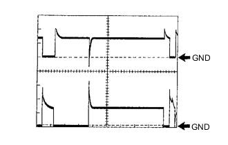
EGR Valve Assembly Operation Signal ECM Terminal Name CH1: Between EGR1 and E1
CH2: Between EGR3 and E1
Tester Range 10 V/DIV., 20 ms./DIV. Condition Engine racing with warm engine -
WAVEFORM 20
Crankshaft Position Sensor Signal ECM Terminal Name Between NE+ and NE- Tester Range 2 V/DIV., 20 ms./DIV. Condition Idling with warm engine Tech Tips
The wavelength becomes shorter as the engine speed increases.
-
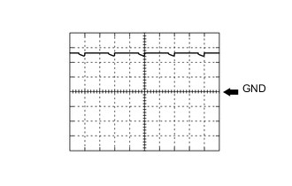
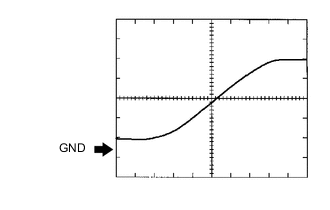
WAVEFORM 21
Knock Sensor Signal ECM Terminal Name Between KNK1 and EKNK Tester Range 1 V/DIV., 1 ms./DIV. Condition Engine speed maintained at 4000 rpm after warming up engine Tech Tips
-
The wavelength becomes shorter as the engine speed increases.
-
The waveforms and amplitudes displayed differ slightly depending on the vehicle condition.
-