SFI SYSTEM Ignition Circuit
DESCRIPTION
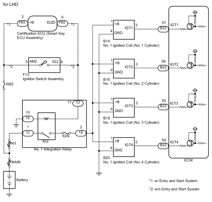
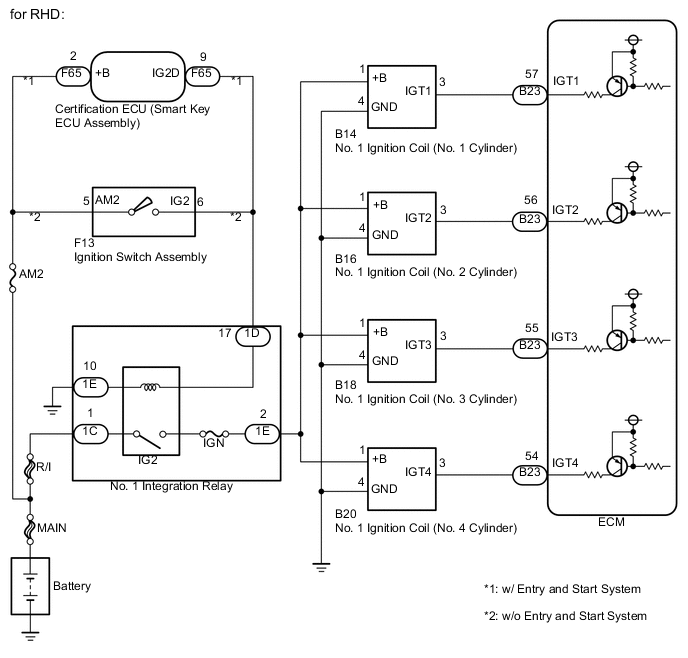
A direct ignition system is used on this vehicle. The direct ignition system is a 1 cylinder ignition system which ignites one cylinder with one No. 1 ignition coil . In the 1 cylinder ignition system, one spark plug is connected to the end of the secondary winding. High voltage is generated in the secondary winding and is applied directly to the spark plug. The spark of the spark plug passes from the center electrode to the ground electrode.
The ECM determines the ignition timing and transmits the ignition signals for each cylinder. Using the ignition signal, the ECM turns ON and OFF the power transistor inside the igniter, which switches ON and OFF a current to the primary coil. When the current to the primary coil is cut off, high voltage is generated in the secondary coil and this voltage is applied to the spark plugs to create sparks inside the cylinders.
WIRING DIAGRAM
CAUTION / NOTICE / HINT
Note
Inspect the fuses for circuits related to this system before performing the following inspection procedure.
PROCEDURE
-
CHECK TERMINAL VOLTAGE (POWER SOURCE OF NO. 1 IGNITION COIL)
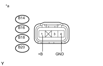
Text in Illustration *a Front view of wire harness connector
(to No. 1 Ignition Coil)
-
Disconnect the No. 1 ignition coil connector.
-
Turn the ignition switch to ON.
-
Measure the voltage according to the value(s) in the table below.
Standard Voltage Tester Connection Switch Condition Specified Condition B14-1 (+B) - B14-4 (GND) Ignition switch ON 11 to 14 V B16-1 (+B) - B16-4 (GND) Ignition switch ON 11 to 14 V B18-1 (+B) - B18-4 (GND) Ignition switch ON 11 to 14 V B20-1 (+B) - B20-4 (GND) Ignition switch ON 11 to 14 V
NG 
CHECK HARNESS AND CONNECTOR (NO. 1 IGNITION COIL - BODY GROUND) Click here
OK 
-
-
CHECK HARNESS AND CONNECTOR (NO. 1 IGNITION COIL - ECM)
-
Disconnect the ECM connector.
-
Disconnect the No. 1 ignition coil connector.
-
Measure the resistance according the value(s) in the table below.
Standard Resistance for LHD Tester Connection Condition Specified Condition B22-57 (IGT1) - B14-3 (IGT1) Always Below 1 Ω B22-56 (IGT2) - B16-3 (IGT2) Always Below 1 Ω B22-55 (IGT3) - B18-3 (IGT3) Always Below 1 Ω B22-54 (IGT4) - B20-3 (IGT4) Always Below 1 Ω B22-57 (IGT1) or B14-3 (IGT1) - Body ground Always 10 kΩ or higher B22-56 (IGT2) or B16-3 (IGT2) - Body ground Always 10 kΩ or higher B22-55 (IGT3) or B18-3 (IGT3) - Body ground Always 10 kΩ or higher B22-54 (IGT4) or B20-3 (IGT4) - Body ground Always 10 kΩ or higher for RHD Tester Connection Condition Specified Condition B23-57 (IGT1) - B14-3 (IGT1) Always Below 1 Ω B23-56 (IGT2) - B16-3 (IGT2) Always Below 1 Ω B23-55 (IGT3) - B18-3 (IGT3) Always Below 1 Ω B23-54 (IGT4) - B20-3 (IGT4) Always Below 1 Ω B23-57 (IGT1) or B14-3 (IGT1) - Body ground Always 10 kΩ or higher B23-56 (IGT2) or B16-3 (IGT2) - Body ground Always 10 kΩ or higher B23-55 (IGT3) or B18-3 (IGT3) - Body ground Always 10 kΩ or higher B23-54 (IGT4) or B20-3 (IGT4) - Body ground Always 10 kΩ or higher
OK 
REPLACE ECM Click here
NG
REPAIR OR REPLACE HARNESS OR CONNECTOR
-
-
CHECK HARNESS AND CONNECTOR (NO. 1 IGNITION COIL - BODY GROUND)
-
Disconnect the No. 1 ignition coil connector.
-
Measure the resistance according to the value(s) in the table below.
Standard Resistance Tester Connection Condition Specified Condition B14-4 (GND) - Body ground Always Below 1 Ω B16-4 (GND) - Body ground Always Below 1 Ω B18-4 (GND) - Body ground Always Below 1 Ω B20-4 (GND) - Body ground Always Below 1 Ω
NG
REPAIR OR REPLACE HARNESS OR CONNECTOR
OK
-
-
CHECK HARNESS AND CONNECTOR (NO. 1 IGNITION COIL - NO. 1 INTEGRATION RELAY)
-
Disconnect the No. 1 ignition coil connector.
-
Remove the No. 1 integration relay from the engine room relay block.
-
Disconnect the No. 1 integration relay connector.
-
Measure the resistance according to the value(s) in the table below.
Standard Resistance Tester Connection Condition Specified Condition B14-1 (+B) - 1E-2 Always Below 1 Ω B16-1 (+B) - 1E-2 Always Below 1 Ω B18-1 (+B) - 1E-2 Always Below 1 Ω B20-1 (+B) - 1E-2 Always Below 1 Ω B14-1 (+B) or 1E-2 - Body ground Always 10 kΩ or higher B16-1 (+B) or 1E-2 - Body ground Always 10 kΩ or higher B18-1 (+B) or 1E-2 - Body ground Always 10 kΩ or higher B20-1 (+B) or 1E-2 - Body ground Always 10 kΩ or higher
NG
REPAIR OR REPLACE HARNESS OR CONNECTOR
OK
-
-
INSPECT NO. 1 INTEGRATION RELAY (IG2 RELAY)
-
Inspect the No. 1 integration relay Click here.
OK
CHECK ECM POWER SOURCE CIRCUIT Click here
NG
REPLACE NO. 1 INTEGRATION RELAY Click here
-