SFI SYSTEM Cranking Holding Function Circuit
DESCRIPTION
-
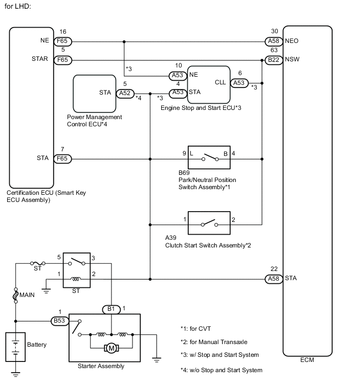
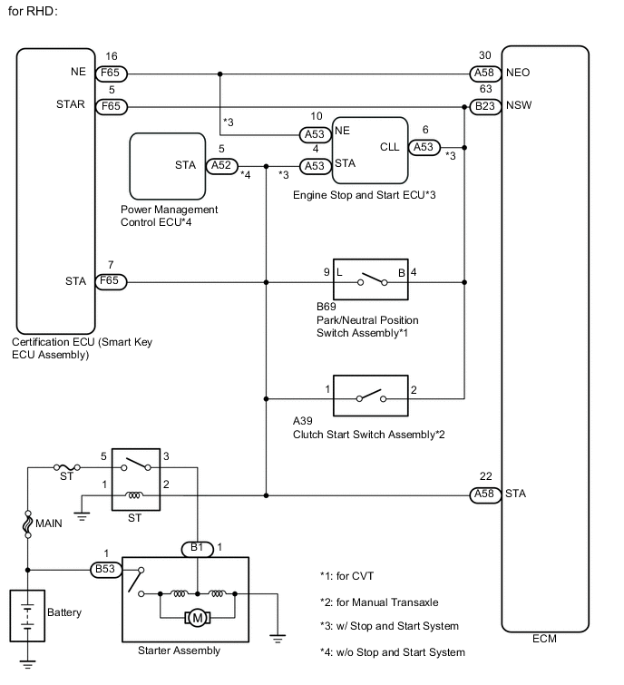
The cranking holding control system keeps energizing the starter relay from when the certification ECU (smart key ECU assembly) detects the starter signal from the ignition switch until the certification ECU performs a judgment of "Engine started".
-
When the certification ECU detects the STSW signal, the certification ECU outputs the starter relay drive signal (STAR signal) to the starter relay through the clutch start switch or park/neutral position switch, and then, the engine is cranked. When the certification ECU receives a stable engine speed signal (NE signal), more specifically, when the NE signal reaches a predetermined value, the certification ECU stops outputting the STAR signal.
-
Also, the certification ECU monitors the starter relay operating conditions based on the STA terminal voltage status.
w/ Entry and Start System
WIRING DIAGRAM
CAUTION / NOTICE / HINT
Note
Inspect the fuses for circuits related to this system before performing the following inspection procedure.
Tech Tips
This chart is based on the premise that the engine can crank normally. If the engine cannot crank normally, proceed to Problem Symptoms Table Click here.
PROCEDURE
-
READ VALUE USING INTELLIGENT TESTER (STARTER SIGNAL)
-
Connect the intelligent tester to the DLC3.
-
Turn the ignition switch to ON.
-
Turn the tester on.
-
Enter the following menus: Powertrain / Engine and ECT / Data List / Starter Signal.
-
Read the value displayed on the tester when the ignition switch is turned to the ON and START positions.
OK Ignition Switch Position Starter Signal ON Close (OFF) START Open (ON)
OK 
PROCEED TO NEXT SUSPECTED AREA SHOWN IN PROBLEM SYMPTOMS TABLE Click here
NG 
-
-
CHECK ST RELAY (POWER SOURCE)
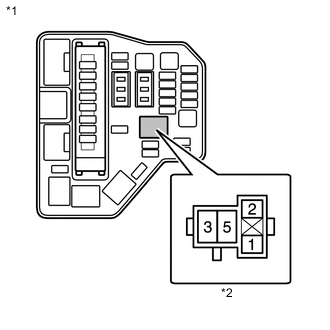
Text in Illustration *1 Engine room relay Block *2 ST Relay Holder
-
Remove the ST relay from the engine room relay block.
-
Measure the voltage according to the value(s) in the table below.
Standard Voltage Tester Connection Condition Specified Condition 2 (ST relay holder) - Body ground Engine cranking 11 to 14 V Result Result Proceed to OK A NG (for Manual Transaxle) B NG (for CVT) C
B 
INSPECT CLUTCH START SWITCH ASSEMBLY Click here
C
INSPECT PARK/NEUTRAL POSITION SWITCH ASSEMBLY Click here
A
-
-
INSPECT ST RELAY
-
Inspect the ST relay Click here.
NG
REPLACE ST RELAY
OK
-
-
CHECK HARNESS AND CONNECTOR (ST RELAY - BODY GROUND)
-
Remove the ST relay from the engine room relay block.
-
Measure the resistance according to the value(s) in the table below.
Standard Resistance Tester Connection Condition Specified Condition 1 (ST relay holder) - Body ground Always 10 kΩ or higher Result Result Proceed to NG A OK (for Manual Transaxle) B OK (for CVT) C
A
REPAIR OR REPLACE HARNESS OR CONNECTOR
B
REPAIR OR REPLACE HARNESS OR CONNECTOR (ECM - CLUTCH START SWITCH ASSEMBLY)
C
REPAIR OR REPLACE HARNESS OR CONNECTOR (ECM - PARK/NEUTRAL POSITION SWITCH ASSEMBLY)
-
-
INSPECT CLUTCH START SWITCH ASSEMBLY
-
Inspect the clutch start switch assembly Click here.
NG
REPLACE CLUTCH START SWITCH ASSEMBLY Click here
OK
-
-
CHECK HARNESS AND CONNECTOR (ECM - CLUTCH START SWITCH ASSEMBLY)
-
Disconnect the ECM connector.
-
Disconnect the clutch start switch assembly connector.
-
Measure the resistance according to the value(s) in the table below.
Standard Resistance Tester Connection Condition Specified Condition A58-22 (STA) - A39-1 Always Below 1 Ω A58-22 (STA) or A39-1 - Body ground Always 10 kΩ or higher
NG
REPAIR OR REPLACE HARNESS OR CONNECTOR
OK
-
-
CHECK HARNESS AND CONNECTOR (CERTIFICATION ECU - CLUTCH START SWITCH ASSEMBLY)
-
Disconnect the certification ECU (smart key ECU assembly) connector.
-
Disconnect the clutch start switch assembly connector.
-
Measure the resistance according to the value(s) in the table below.
Standard Resistance Tester Connection Condition Specified Condition F65-5 (STAR) - A39-2 Always Below 1 Ω F65-5 (STAR) or A39-2 - Body ground Always 10 kΩ or higher
OK
CHECK ENTRY AND START SYSTEM (for Start Function) Click here
NG
REPAIR OR REPLACE HARNESS OR CONNECTOR
-
-
INSPECT PARK/NEUTRAL POSITION SWITCH ASSEMBLY
-
Inspect the park/neutral position switch assembly Click here.
NG
REPLACE PARK/NEUTRAL POSITION SWITCH ASSEMBLY Click here
OK
-
-
CHECK HARNESS AND CONNECTOR (ECM - PARK/NEUTRAL POSITION SWITCH ASSEMBLY)
-
Disconnect the ECM connector.
-
Disconnect the park/neutral position switch assembly connector.
-
Measure the resistance according to the value(s) in the table below.
Standard Resistance Tester Connection Condition Specified Condition A58-22 (STA) - B69-9 (L) Always Below 1 Ω A58-22 (STA) or B69-9 (L) - Body ground Always 10 kΩ or higher
NG
REPAIR OR REPLACE HARNESS OR CONNECTOR
OK
-
-
CHECK HARNESS AND CONNECTOR (CERTIFICATION ECU - PARK/NEUTRAL POSITION SWITCH ASSEMBLY)
-
Disconnect the certification ECU (smart key ECU assembly) connector.
-
Disconnect the park/neutral position switch assembly connector.
-
Measure the resistance according to the value(s) in the table below.
Standard Resistance Tester Connection Condition Specified Condition F65-5 (STAR) - B69-4 (B) Always Below 1 Ω F65-5 (STAR) or B69-4 (B) - Body ground Always 10 kΩ or higher
OK
CHECK ENTRY AND START SYSTEM (for Start Function) Click here
NG
REPAIR OR REPLACE HARNESS OR CONNECTOR
-