SFI SYSTEM Starter Signal Circuit
DESCRIPTION
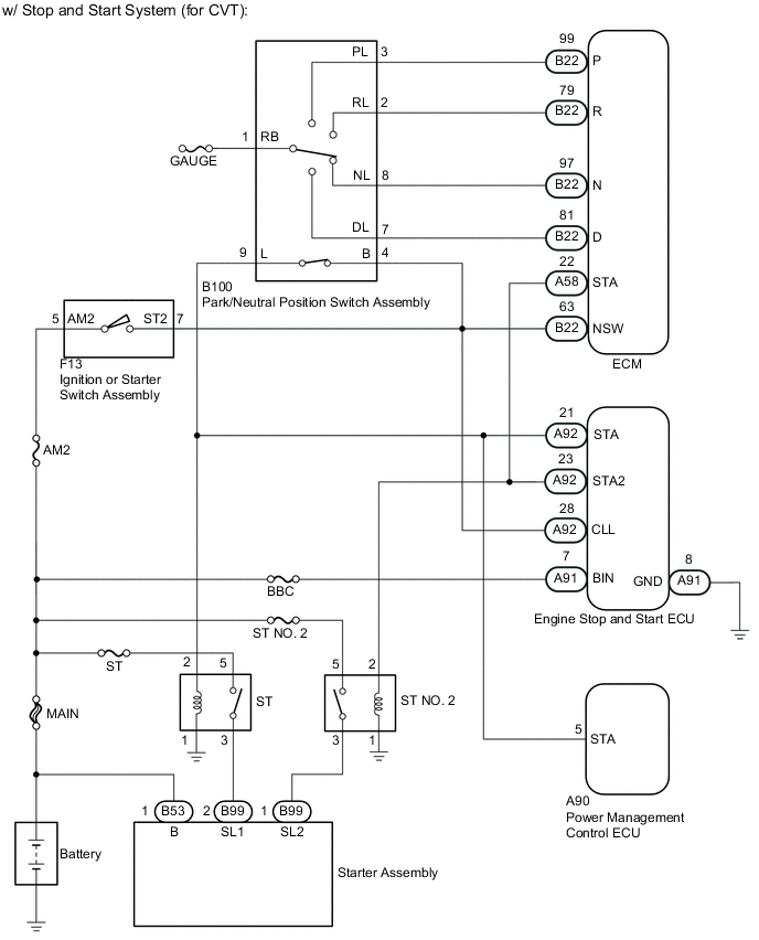
- w/ Stop and Start System (for CVT)
When cranking, the ECM detects the starter motor drive signal (STA2 signal) from the engine stop and start ECU as the starter signal (STA signal) and performs engine control when starting. When the start signal is input from the ignition switch, the drive signal (STAR signal) is sent through the Park/neutral position switch to the ST relay (for starter pinion operation), and then the starter motor drive signal (STA2) is sent by the delay circuit inside the engine stop and start ECU to the ST No. 2 relay (for starter motor operation), and drives the starter until a full engine start (NE signal) is detected.
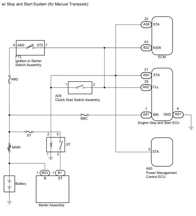
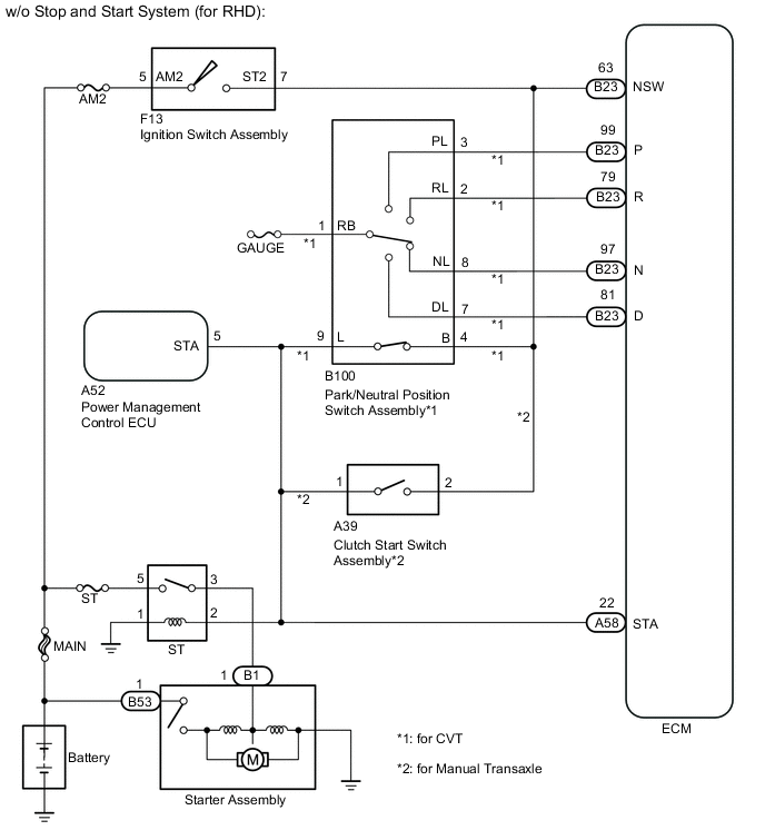
- w/ Stop and Start System (for Manual Transaxle), w/o Stop and Start System
While the engine is being cranked, current flows from terminal ST2 of the ignition switch to the park/neutral position switch*1 or the clutch start switch assembly*2 and also flows to terminal STA of the ECM (STA Signal).
-
*1: for CVT
-
*2: for Manual Transaxle
-
WIRING DIAGRAM

CAUTION / NOTICE / HINT
Note
-
Inspect the fuses for circuits related to this system before performing the following inspection procedure.
-
After turning ignition switch off, waiting time may be required before disconnecting the cable from the negative (-) battery terminal. Therefore, make sure to read the disconnecting the cable from the negative (-) battery terminal notices before proceeding with work Click here.
PROCEDURE
-
SYSTEM CHECK
-
Check the vehicle specifications.
Result Result Proceed to w/ Stop and Start System for CVT A for Manual Transaxle B w/o Stop and Start System C
B 
CHECK WHETHER ENGINE STARTS Click here
C
CHECK WHETHER ENGINE CAN BE CRANKED Click here
A 
-
-
CHECK WHETHER ENGINE STARTS
-
Check if the engine can be cranked.
Result Result Proceed to Engine cannot be cranked A Engine can be cranked B
B
READ VALUE USING INTELLIGENT TESTER (STARTER SIGNAL) Click here
A
-
-
READ VALUE USING INTELLIGENT TESTER (STARTER SIGNAL)
-
Connect the intelligent tester to the DLC3.
-
Turn the ignition switch to ON.
-
Turn the tester on.
-
Enter the following menus: Powertrain / Engine and ECT / Data List / Starter Signal.
-
Read the value displayed on the tester when the ignition switch is turned to the ON and START positions.
OK Ignition Switch Position Starter Signal ON OFF START ON
NG 
GO TO STOP AND START SYSTEM Click here
OK
-
-
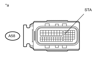
CHECK HARNESS AND CONNECTOR (ECM - ENGINE STOP AND START ECU - ST NO. 2 RELAY)
-
Disconnect the A58 ECM connector.
-
Disconnect the A92 engine stop and start ECU connector.
-
Remove the ST NO. 2 relay from the NO. 2 engine room relay block.
-
Measure the resistance according to the value(s) in the table below.
Standard Resistance Tester Connection Condition Specified Condition A58-22 (STA) - A92-23 (STA2) Always Below 1 Ω A58-22 (STA) - Relay holder 2 Always Below 1 Ω 58-22 (STA), 92-23 (STA2) or Relay holder 2 - Body ground Always 10 kΩ or higher
NG
REPAIR OR REPLACE HARNESS OR CONNECTOR
OK
-
-
CHECK HARNESS AND CONNECTOR (ECM - ENGINE STOP AND START ECU - PARK/NEUTRAL POSITION SWITCH - IGNITION SWITCH ASSEMBLY)
-
Disconnect the B22 ECM connector.
-
Disconnect the A92 engine stop and start ECU connector.
-
Disconnect the B100 park/neutral position switch connector.
-
Disconnect the F13 ignition switch assembly connector.
-
Measure the resistance according to the value(s) in the table below.
Standard Resistance Tester Connection Condition Specified Condition B22-63 (NSW) - F13-7 (ST2) Always Below 1 Ω B22-63 (NSW) - B100-4 (B) Always Below 1 Ω B22-63 (NSW) - A92-28 (CLL) Always Below 1 Ω B22-63 (NSW), F13-7 (ST2), B100-4 (B) or A92-28 (CLL) - Body ground Always 10 kΩ or higher
OK
PROCEED TO NEXT SUSPECTED AREA SHOWN IN PROBLEM SYMPTOMS TABLE Click here
NG
REPAIR OR REPLACE HARNESS OR CONNECTOR
-
-
READ VALUE USING INTELLIGENT TESTER (STARTER SIGNAL)
-
Connect the intelligent tester to the DLC3.
-
Turn the ignition switch to ON.
-
Turn the tester on.
-
Enter the following menus: Powertrain / Engine and ECT / Data List / Starter Signal.
-
Read the value displayed on the tester when the ignition switch is turned to the ON and START positions.
OK Ignition Switch Position Starter Signal ON OFF START ON
OK
PROCEED TO NEXT SUSPECTED AREA SHOWN IN PROBLEM SYMPTOMS TABLE Click here
NG
REPAIR OR REPLACE HARNESS OR CONNECTOR (ECM - ST NO. 2 RELAY)
-
-
CHECK WHETHER ENGINE STARTS
-
Check if the engine can be cranked.
Result Result Proceed to Engine cannot be cranked A Engine can be cranked B
B
READ VALUE USING INTELLIGENT TESTER (STARTER SIGNAL) Click here
A
-
-
READ VALUE USING INTELLIGENT TESTER (STARTER SIGNAL)
-
Connect the intelligent tester to the DLC3.
-
Turn the ignition switch to ON.
-
Turn the tester on.
-
Enter the following menus: Powertrain / Engine and ECT / Data List / Starter Signal.
-
Read the value displayed on the tester when the ignition switch is turned to the ON and START positions.
OK Ignition Switch Position Starter Signal ON OFF START ON
NG
READ VALUE USING INTELLIGENT TESTER (STARTER SIGNAL) Click here
OK
-
-
CHECK TERMINAL VOLTAGE (POWER SOURCE OF ST RELAY)
-
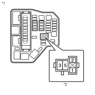
Text in Illustration *1 Engine Room Relay Block *2 Relay holder (ST relay) Remove the ST relay from the engine room relay block.
-
Measure the voltage according to the value(s) in the table below.
Standard Voltage Tester Connection Condition Specified Condition Relay holder 5 - Body ground Always 11 to 14 V
NG
REPAIR OR REPLACE HARNESS OR CONNECTOR (BATTERY - ST RELAY)
OK
-
-
CHECK HARNESS AND CONNECTOR (ST RELAY - BODY GROUND)
-
Remove the ST relay from the engine room relay block.
-
Measure the resistance according to the value(s) in the table below.
Standard Resistance Tester Connection Condition Specified Condition Relay holder 1 - Body ground Always 10 kΩ or higher
NG
REPAIR OR REPLACE HARNESS OR CONNECTOR
OK
-
-
CHECK HARNESS AND CONNECTOR (ST RELAY - STARTER ASSEMBLY)
-
Remove the ST relay from the engine room relay block.
-
Disconnect the B1 starter assembly connector.
-
Measure the resistance according to the value(s) in the table below.
Standard Resistance Tester Connection Condition Specified Condition Relay holder 3 - B1-1 Always Below 1 Ω Relay holder 3 or B1-1 - Body ground Always 10 kΩ or higher
NG
REPAIR OR REPLACE HARNESS OR CONNECTOR
OK
-
-
CHECK HARNESS AND CONNECTOR (BATTERY - STARTER ASSEMBLY)
-
Disconnect the cable from the negative (-) battery terminal.
-
Disconnect the cable from the positive (+) battery terminal.
-
Disconnect the B53 starter assembly connector.
-
Measure the resistance according to the value(s) in the table below.
Standard Resistance Tester Connection Condition Specified Condition Positive (+) battery terminal - B53-1 Always Below 1 Ω
NG
REPAIR OR REPLACE HARNESS OR CONNECTOR
OK
-
-
CHECK HARNESS AND CONNECTOR (ST RELAY - CLUTCH START SWITCH ASSEMBLY)
-
Remove the ST relay from the engine room relay block.
-
Disconnect the A39 clutch start switch assembly connector.
-
Disconnect the A90 power management control ECU connector.
-
Disconnect the A92 engine stop and start ECU connector.
-
Disconnect the A58 ECM connector.
-
Measure the resistance according to the value(s) in the table below.
Standard Resistance Tester Connection Condition Specified Condition Relay holder 2 - A39-1 Always 10 kΩ or higher
OK
PROCEED TO NEXT SUSPECTED AREA SHOWN IN PROBLEM SYMPTOMS TABLE Click here
NG
REPAIR OR REPLACE HARNESS OR CONNECTOR
-
-
READ VALUE USING INTELLIGENT TESTER (STARTER SIGNAL)
-
Disconnect the A90 power management control ECU connector.
-
Connect the intelligent tester to the DLC3.
-
Turn the ignition switch to ON.
-
Turn the tester on.
-
Enter the following menus: Powertrain / Engine and ECT / Data List / Starter Signal.
-
Read the value displayed on the tester when the ignition switch is turned to the ON and START positions.
OK Ignition Switch Position Starter Signal ON OFF START ON
NG
REPLACE POWER MANAGEMENT CONTROL ECU Click here
OK
-
-
CHECK TERMINAL VOLTAGE (POWER SOURCE OF IGNITION SWITCH ASSEMBLY)
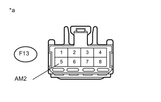
Text in Illustration *a Front view of wire harness connector
(to Ignition Switch Assembly)
-
Disconnect the ignition switch assembly connector.
-
Measure the voltage according to the value(s) in the table below.
Standard Voltage Tester Connection Condition Specified Condition F13-5 (AM2) - Body ground Always 11 to 14 V
NG
REPAIR OR REPLACE HARNESS OR CONNECTOR (IGNITION SWITCH - BATTERY)
OK
-
-
CHECK HARNESS AND CONNECTOR (ECM - IGNITION SWITCH ASSEMBLY - ENGINE STOP AND START ECU - CLUTCH START SWITCH ASSEMBLY)
-
Disconnect the B22 ECM connector
-
Disconnect the F13 ignition switch assembly connector.
-
Disconnect the A92 engine stop and start ECU connector.
-
Disconnect the A39 clutch start switch assembly connector.
-
Measure the resistance according to the value(s) in the table below.
Standard Resistance Tester Connection Condition Specified Condition B22-63 (NSW) - F13-7 (ST2) Always Below 1 Ω B22-63 (NSW) - A92-28 (CLL) Always Below 1 Ω B22-63 (NSW) - A39-2 Always Below 1 Ω B22-63 (NSW), F13-7 (ST2), A92-28 (CLL) or A39-2 - Body ground Always 10 kΩ or higher
NG
REPAIR OR REPLACE HARNESS OR CONNECTOR
OK
-
-
CHECK HARNESS AND CONNECTOR (ECM - ENGINE STOP AND START ECU - POWER MANAGEMENT CONTROL ECU - CLUTCH START SWITCH - ST RELAY)
-
Disconnect the A58 ECM connector.
-
Disconnect the A92 engine stop and start ECU connector.
-
Disconnect the A90 power management control ECU connector.
-
Disconnect the A39 clutch start switch assembly connector.
-
Remove the ST relay from the engine room relay block.
-
Measure the resistance according to the value(s) in the table below.
Standard Resistance Tester Connection Condition Specified Condition A58-22 (STA) - A92-21 (STA) Always Below 1 Ω A58-22 (STA) - A90-5 (STA) Always Below 1 Ω A58-22 (STA) - A39-1 Always Below 1 Ω A58-22 (STA) - Relay holder 2 Always Below 1 Ω A58-22 (STA), A92-21 (STA), A90-5 (STA), A39-1 or Relay holder 2 - Body ground Always 10 kΩ or higher
OK
PROCEED TO NEXT SUSPECTED AREA SHOWN IN PROBLEM SYMPTOMS TABLE Click here
NG
REPAIR OR REPLACE HARNESS OR CONNECTOR
-
-
READ VALUE USING INTELLIGENT TESTER (STARTER SIGNAL)
-
Connect the intelligent tester to the DLC3.
-
Turn the ignition switch to ON.
-
Turn the tester on.
-
Enter the following menus: Powertrain / Engine and ECT / Data List / Starter Signal.
-
Read the value displayed on the tester when the ignition switch is turned to the ON and START positions.
OK Ignition Switch Position Starter Signal ON OFF START ON
OK
PROCEED TO NEXT SUSPECTED AREA SHOWN IN PROBLEM SYMPTOMS TABLE Click here
NG
-
-
CHECK HARNESS AND CONNECTOR (ST RELAY - ECM)
-
Remove the ST relay from the engine room relay block.
-
Disconnect the A58 ECM connector.
-
Disconnect the A39 clutch start switch assembly connector.
-
Disconnect the A90 power management control ECU connector.
-
Measure the resistance according to the value(s) in the table below.
Standard Resistance Tester Connection Condition Specified Condition Relay holder 2 - A58-22 (STA) Always Below 1 Ω
OK
PROCEED TO NEXT SUSPECTED AREA SHOWN IN PROBLEM SYMPTOMS TABLE Click here
NG
REPAIR OR REPLACE HARNESS OR CONNECTOR
-
-
CHECK WHETHER ENGINE CAN BE CRANKED
-
Check if the engine can be cranked.
Result Result Proceed to Engine cannot be cranked A Engine can be cranked B
B
READ VALUE USING INTELLIGENT TESTER (STARTER SIGNAL) Click here
A
-
-
READ VALUE USING INTELLIGENT TESTER (STARTER SIGNAL)
-
Connect the intelligent tester to the DLC3.
-
Turn the ignition switch to ON.
-
Turn the tester on.
-
Enter the following menus: Powertrain / Engine and ECT / Data List / Starter Signal.
-
Read the value displayed on the tester when the ignition switch is turned to the ON and START positions.
OK Ignition Switch Position Starter Signal ON OFF START ON
B
CHECK TERMINAL VOLTAGE (POWER SOURCE OF ST RELAY) Click here
A
-
-
CHECK TERMINAL VOLTAGE (POWER SOURCE OF IGNITION SWITCH ASSEMBLY)
-
Disconnect the ignition switch assembly connector
-
Measure the voltage according to the value(s) in the table below.
Standard Voltage Tester Connection Condition Specified Condition F13-5 (AM2) - Body ground Always 11 to 14 V Text in Illustration *a Front view of wire harness connector
(to Ignition Switch Assembly)
Result Result Proceed to NG (for CVT) A NG (for Manual Transaxle) B OK C
B
CHECK HARNESS AND CONNECTOR (ECM - CLUTCH START SWITCH ASSEMBLY - IGNITION SWITCH ASSEMBLY) Click here
C
REPAIR OR REPLACE HARNESS OR CONNECTOR (IGNITION SWITCH ASSEMBLY - BATTERY)
A
-
-
CHECK HARNESS AND CONNECTOR (ECM - PARK/NEUTRAL POSITION SWITCH - IGNITION SWITCH ASSEMBLY)
-
Disconnect the B22 ECM connector (for LHD).
-
Disconnect the B23 ECM connector (for RHD).
-
Disconnect the B100 park/neutral position switch connector.
-
Disconnect the F13 ignition switch assembly connector.
-
Measure the resistance according to the value(s) in the table below.
Standard Resistance for LHD Tester Connection Condition Specified Condition B22-63 (NSW) - F13-7 (ST2) Always Below 1 Ω B22-63 (NSW) - B100-4 (B) Always Below 1 Ω B22-63 (NSW), F13-7 (ST2), or B100-4 (B) - Body ground Always 10 kΩ or higher for RHD Tester Connection Condition Specified Condition B23-63 (NSW) - F13-7 (ST2) Always Below 1 Ω B23-63 (NSW) - B100-4 (B) Always Below 1 Ω B23-63 (NSW), F13-7 (ST2), or B100-4 (B) - Body ground Always 10 kΩ or higher
NG
REPAIR OR REPLACE HARNESS OR CONNECTOR
OK
-
-
CHECK HARNESS AND CONNECTOR (ECM - PARK/NEUTRAL POSITION SWITCH - ST RELAY - POWER MANAGEMENT CONTROL ECU)
-
Disconnect the A58 ECM connector.
-
Disconnect the B100 park/neutral position switch connector.
-
Remove the ST relay from the engine room relay block.
-
Disconnect the A52 power management control ECU connector.
-
Measure the resistance according to the value(s) in the table below.
Standard Resistance Tester Connection Condition Specified Condition A58-22 (STA) - B100-9 (L) Always Below 1 Ω A58-22 (STA) - A52-5 (STA) Always Below 1 Ω A58-22 (STA) - Relay holder 2 Always Below 1 Ω A58-22 (STA), B100-9 (L), A52-5 (STA) or Relay holder 2 - Body ground Always 10 kΩ or higher
B
REPAIR OR REPLACE HARNESS OR CONNECTOR
OK
-
-
CHECK POWER MANAGEMENT CONTROL ECU
Text in Illustration *a Front view of wire harness connector
(to ECM)
-
Disconnect the ECM connector.
-
Disconnect the B100 park/neutral position switch connector.
-
Remove the ST relay from the engine room relay block.
-
Measure the resistance according to the value(s) in the table below.
Standard Resistance Tester Connection Condition Specified Condition A58-22 (STA) - Body ground Always 10 kΩ or higher
A
PROCEED TO NEXT SUSPECTED AREA SHOWN IN PROBLEM SYMPTOMS TABLE Click here
B
REPLACE POWER MANAGEMENT CONTROL ECU Click here
-
-
CHECK HARNESS AND CONNECTOR (ECM - CLUTCH START SWITCH ASSEMBLY - IGNITION SWITCH ASSEMBLY)
-
Disconnect the B22 ECM connector (for LHD).
-
Disconnect the B23 ECM connector (for RHD).
-
Disconnect the A39 clutch start switch assembly connector.
-
Disconnect the F13 ignition switch assembly connector.
-
Measure the resistance according to the value(s) in the table below.
Standard Resistance for LHD Tester Connection Condition Specified Condition B22-63 (NSW) - F13-7 (ST2) Always Below 1 Ω B22-63 (NSW) - A39-2 Always Below 1 Ω B22-63 (NSW), F13-7 (ST2), or A39-2 - Body ground Always 10 kΩ or higher for RHD Tester Connection Condition Specified Condition B23-63 (NSW) - F13-7 (ST2) Always Below 1 Ω B23-63 (NSW) - A39-2 Always Below 1 Ω B23-63 (NSW), F13-7 (ST2), or A39-2 - Body ground Always 10 kΩ or higher
NG
REPAIR OR REPLACE HARNESS OR CONNECTOR
OK
-
-
CHECK HARNESS AND CONNECTOR (ECM - CLUTCH START SWITCH ASSEMBLY - POWER MANAGEMENT CONTROL ECU - ST RELAY)
-
Disconnect the A58 ECM connector.
-
Disconnect the A39 clutch start switch assembly connector.
-
Disconnect the A52 power management control ECU connector.
-
Remove the ST relay from the engine room relay block.
-
Measure the resistance according to the value(s) in the table below.
Standard Resistance Tester Connection Condition Specified Condition A58-22 (STA) - A39-1 Always Below 1 Ω A58-22 (STA) - A52-5 (STA) Always Below 1 Ω A58-22 (STA) - Relay holder 2 Always Below 1 Ω A58-22 (STA), A39-1, A52-5 (STA) or Relay holder 2 - Body ground Always 10 kΩ or higher
NG
REPAIR OR REPLACE HARNESS OR CONNECTOR
OK
-
-
CHECK POWER MANAGEMENT CONTROL ECU
Text in Illustration *a Front view of wire harness connector
(to ECM)
-
Disconnect the ECM connector.
-
Disconnect the A39 clutch start switch assembly connector.
-
Remove the ST relay from the engine room relay block.
-
Measure the resistance according to the value(s) in the table below.
Standard Resistance Tester Connection Condition Specified Condition A58-22 (STA) - Body ground Always 10 kΩ or higher
OK
PROCEED TO NEXT SUSPECTED AREA SHOWN IN PROBLEM SYMPTOMS TABLE Click here
NG
REPLACE POWER MANAGEMENT CONTROL ECU Click here
-
-
CHECK TERMINAL VOLTAGE (POWER SOURCE OF ST RELAY)
-
Text in Illustration *1 Engine Room Relay Block *2 Relay holder (ST relay) Remove the ST relay from the engine room relay block.
-
Measure the voltage according to the value(s) in the table below.
Standard Voltage Tester Connection Condition Specified Condition Relay holder 5 - Body ground Always 11 to 14 V Result Result Proceed to OK (for Manual Transaxle) A OK (for CVT) B NG C
NG
REPAIR OR REPLACE HARNESS OR CONNECTOR (ST RELAY - BATTERY)
OK
-
-
CHECK HARNESS AND CONNECTOR (ST RELAY - BODY GROUND)
-
Remove the ST relay from the engine room relay block.
-
Measure the resistance according to the value(s) in the table below.
Standard Resistance Tester Connection Condition Specified Condition Relay holder 1 - Body ground Always 10 kΩ or higher
NG
REPAIR OR REPLACE HARNESS OR CONNECTOR
OK
-
-
CHECK HARNESS AND CONNECTOR (ST RELAY - STARTER ASSEMBLY)
-
Remove the ST relay from the engine room relay block.
-
Disconnect the B1 starter assembly connector.
-
Measure the resistance according to the value(s) in the table below.
Standard Resistance Tester Connection Condition Specified Condition Relay holder 3 - B1-1 Always Below 1 Ω Relay holder 3 or B1-1 - Body ground Always 10 kΩ or higher
NG
REPAIR OR REPLACE HARNESS OR CONNECTOR
OK
-
-
CHECK HARNESS AND CONNECTOR (BATTERY - STARTER ASSEMBLY)
-
Disconnect the cable from the negative (-) battery terminal.
-
Disconnect the cable from the positive (+) battery terminal.
-
Disconnect the B53 starter assembly connector.
-
Measure the resistance according to the value(s) in the table below.
Standard Resistance Tester Connection Condition Specified Condition Positive (+) battery terminal - B53-1 Always Below 1 Ω
B
CHECK HARNESS AND CONNECTOR (ST RELAY - CLUTCH START SWITCH ASSEMBLY) Click here
C
REPAIR OR REPLACE HARNESS OR CONNECTOR
A
-
-
CHECK HARNESS AND CONNECTOR (ST RELAY - PARK/NEUTRAL POSITION SWITCH)
-
Remove the ST relay from the engine room relay block.
-
Disconnect the B100 park/neutral position switch assembly connector.
-
Disconnect the A52 power management control ECU connector.
-
Disconnect the A58 ECM connector.
-
Measure the resistance according to the value(s) in the table below.
Standard Resistance Tester Connection Condition Specified Condition Relay holder 2 - A39-1 Always 10 kΩ or higher
OK
PROCEED TO NEXT SUSPECTED AREA SHOWN IN PROBLEM SYMPTOMS TABLE Click here
NG
REPAIR OR REPLACE HARNESS OR CONNECTOR
-
-
CHECK HARNESS AND CONNECTOR (ST RELAY - CLUTCH START SWITCH ASSEMBLY)
-
Remove the ST relay from the engine room relay block.
-
Disconnect the A39 clutch start switch assembly connector.
-
Disconnect the A52 power management control ECU connector.
-
Disconnect the A58 ECM connector.
-
Measure the resistance according to the value(s) in the table below.
Standard Resistance Tester Connection Condition Specified Condition Relay holder 2 - A39-1 Always 10 kΩ or higher
OK
PROCEED TO NEXT SUSPECTED AREA SHOWN IN PROBLEM SYMPTOMS TABLE Click here
NG
REPAIR OR REPLACE HARNESS OR CONNECTOR
-
-
READ VALUE USING INTELLIGENT TESTER (STARTER SIGNAL)
-
Connect the intelligent tester to the DLC3.
-
Turn the ignition switch to ON.
-
Turn the tester on.
-
Enter the following menus: Powertrain / Engine and ECT / Data List / Starter Signal.
-
Read the value displayed on the tester when the ignition switch is turned to the ON and START positions.
OK Ignition Switch Position Starter Signal ON OFF START ON Result Result Proceed to OK A NG (for CVT) B NG (for Manual Transaxle) C
A
PROCEED TO NEXT SUSPECTED AREA SHOWN IN PROBLEM SYMPTOMS TABLE Click here
C
CHECK HARNESS AND CONNECTOR (ST RELAY - ECM) Click here
B
-
-
CHECK HARNESS AND CONNECTOR (ST RELAY - ECM)
-
Remove the ST relay from the engine room relay block.
-
Disconnect the A58 ECM connector.
-
Disconnect the B100 park/neutral position switch assembly connector.
-
Disconnect the A52 power management control ECU connector.
-
Measure the resistance according to the value(s) in the table below.
Standard Resistance Tester Connection Condition Specified Condition Relay holder 2 - A58-22 (STA) Always Below 1 Ω
OK
PROCEED TO NEXT SUSPECTED AREA SHOWN IN PROBLEM SYMPTOMS TABLE Click here
NG
REPAIR OR REPLACE HARNESS OR CONNECTOR
-
-
CHECK HARNESS AND CONNECTOR (ST RELAY - ECM)
-
Remove the ST relay from the engine room relay block.
-
Disconnect the A58 ECM connector.
-
Disconnect the A39 clutch start switch assembly connector.
-
Disconnect the A52 power management control ECU connector.
-
Measure the resistance according to the value(s) in the table below.
Standard Resistance Tester Connection Condition Specified Condition Relay holder 2 - A58-22 (STA) Always Below 1 Ω
OK
PROCEED TO NEXT SUSPECTED AREA SHOWN IN PROBLEM SYMPTOMS TABLE Click here
NG
REPAIR OR REPLACE HARNESS OR CONNECTOR
-