AIR FUEL RATIO SENSOR(for Sensor 1) INSTALLATION

PROCEDURE
-
INSTALL AIR FUEL RATIO SENSOR (w/ DPF)
Tech Tips
Perform "Inspection After Repair" after replacing the air fuel ratio sensor Click here.
-
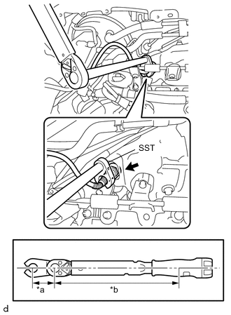
Text in Illustration *a SST Fulcrum Length *b Torque Wrench Fulcrum Length Using SST, install the air fuel ratio sensor to the exhaust manifold.
- SST
- 09224-00010
- Torque:
- Specified tightening torque
- 44 N*m { 449 kgf*cm, 32 ft.*lbf }
Note
If a component has been dropped or subjected to a strong impact, replace the air fuel ratio sensor.
Tech Tips
-
Calculate the torque wrench reading when changing the fulcrum length of the torque wrench (Seepage Click here).
-
When using SST (fulcrum length of 30 (1.18 in)) + torque wrench (fulcrum length of 300 (11.81 in)): 40 N*m (408 kgf*cm, 30 ft.*lbf).
-
-
INSTALL AIR FUEL RATIO SENSOR (w/o DPF)
Tech Tips
Perform "Inspection After Repair" after replacing the air fuel ratio sensor Click here.
-
Using SST, install the air fuel ratio sensor onto the exhaust manifold converter sub-assembly.
- SST
- 09224-00010
- Torque:
- Specified tightening torque
- 44 N*m { 449 kgf*cm, 32 ft.*lbf }
Note
If a component has been dropped or subjected to a strong impact, replace the air fuel ratio sensor.
Tech Tips
-
Calculate the torque wrench reading when changing the fulcrum length of the torque wrench (Seepage Click here).
-
When using SST (fulcrum length of 30 (1.18 in)) + torque wrench (fulcrum length of 300 (11.81 in)): 40 N*m (408 kgf*cm, 30 ft.*lbf).
-
-
INSTALL WIRING HARNESS CLAMP BRACKET (w/ DPF)
-
INSTALL NO. 1 WIRING HARNESS HEAT INSULATOR (w/ DPF)
-
INSTALL WIRING HARNESS CLAMP BRACKET (w/o DPF)
-
Install the wiring harness clamp bracket to the cylinder head cover sub-assembly.
-
Engage the 5 clamps to connect the wire harness to the wire harness clamp bracket.
-
Connect the air fuel ratio sensor connector.
-
-
INSTALL NO. 2 ENGINE COVER BRACKET (w/o DPF)
-
Install the No. 2 engine cover bracket to the cylinder head cover sub-assembly with the 2 nuts.
- Torque:
- 11 N*m { 112 kgf*cm, 8 ft.*lbf }
-
-
INSTALL OUTER COWL TOP PANEL (for LHD)
-
INSTALL OUTER COWL TOP PANEL (for RHD)
-
INSTALL INNER COWL TOP TO COWL BRACE (for LHD)
-
INSTALL INNER COWL TOP TO COWL BRACE (for RHD)
-
INSTALL FRONT AIR SHUTTER SEAL RH (for LHD)
-
INSTALL FRONT AIR SHUTTER SEAL RH (for RHD)
-
INSTALL FRONT NO. 1 VENTILATOR SEAL (for LHD)
-
INSTALL FRONT NO. 1 VENTILATOR SEAL (for RHD)
-
INSTALL FRONT WIPER MOTOR AND LINK
-
INSPECT FOR EXHAUST GAS LEAK
-
INSTALL NO. 1 ENGINE COVER