ECD SYSTEM(w/o DPF), Diagnostic DTC:P0504
| DTC Code | DTC Name |
|---|---|
| P0504 | Brake Switch "A" / "B" Correlation |
DESCRIPTION
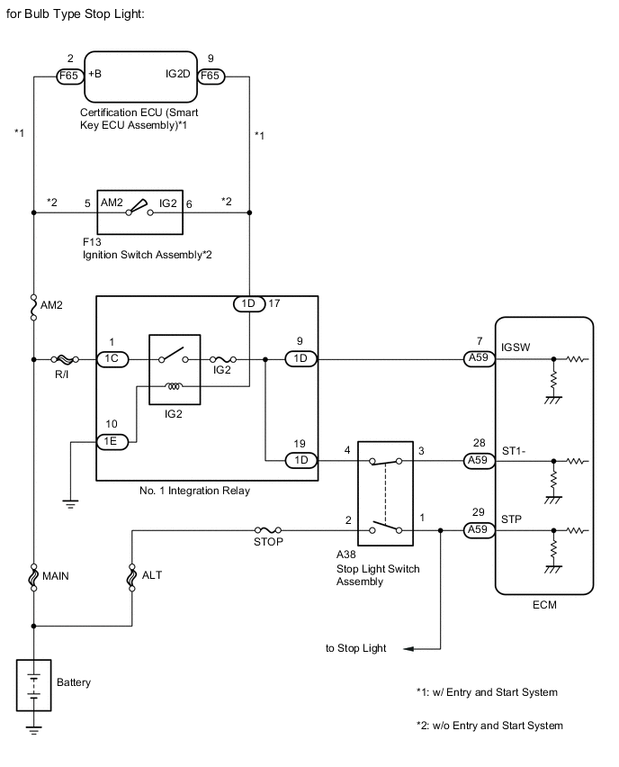
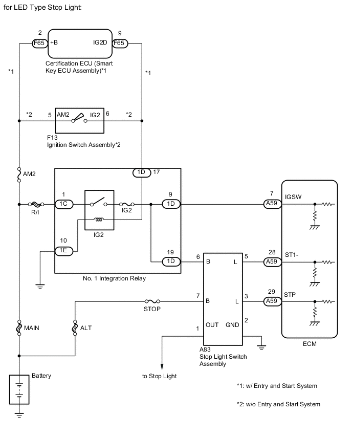
The stop light switch is a duplex system that transmits two signals: STP and ST1-. These two signals are used by the ECM to monitor whether or not the brake system is working properly. If the signals, which indicate that the brake pedal is being depressed and released, are detected simultaneously, the ECM interprets this as a malfunction in the stop light switch and stores the DTC.
Tech Tips
The normal conditions are as shown in the table below.
| Signal (ECM terminal) | Brake Pedal Released | In Transition | Brake Pedal Depressed |
|---|---|---|---|
| STP | OFF | ON | ON |
| ST1- | ON | ON | OFF |
-
[OFF] denotes ground potential.
-
[ON] denotes battery potential (+B).
-
On the intelligent tester, both the Data List items Stop Light Switch and ST1 are ON when the brake pedal is depressed because the ST1 indication characteristic is opposite to the Stop Light Switch indication.
| DTC Detection Drive Pattern | DTC Detection Condition | Trouble Area |
|---|---|---|
| Release and depress brake pedal with ignition switch ON. |
|
|
| DTC No. | Data List |
|---|---|
| P0504 | Stop Light Switch |
WIRING DIAGRAM
CAUTION / NOTICE / HINT
Note
-
When replacing the ECM, the ECM needs Registration and Initialization Click here.
-
Inspect the fuses for circuits related to this system before performing the following inspection procedure.
Tech Tips
-
When the ECM must be replaced, before replacing the ECM, perform the "Learning Values Save" function using the intelligent tester. Then after installing the new ECM, perform all of the initialization/registrations for the "Learning Values Write" function by following the instructions shown on the tester display.
-
Read freeze frame data using the intelligent tester. Freeze frame data records the engine condition when malfunctions are detected. When troubleshooting, freeze frame data can help determine if the vehicle was moving or stationary, if the engine was warmed up or not, and other data from the time the malfunction occurred.
-
Stop light switch assembly conditions can be checked using the intelligent tester.
-
Connect the intelligent tester to the DLC3.
-
Turn the ignition switch to ON and turn the tester on.
-
Enter the following menus: Powertrain / Engine and ECT / Data List / Stop Light Switch and ST1.
-
Check Stop Light Switch when the brake pedal is depressed and released.
Brake Pedal Operation Stop Light Switch ST1 Depressed ON ON Released OFF OFF
PROCEDURE
-
READ VALUE USING INTELLIGENT TESTER (STOP LIGHT SWITCH)
-
Connect the intelligent tester to the DLC3.
-
Turn the ignition switch to ON.
-
Turn the tester on.
-
Enter the following menus: Powertrain / Engine and ECT / Data List / Stop Light Switch.
-
Read the value displayed on the tester.
OK Condition Specified Condition Brake pedal depressed STP signal ON Brake pedal released STP signal OFF Result Result Proceed to OK A NG (for Bulb Type Stop Light) B NG (for LED Type Stop Light) C
A 
CHECK FOR INTERMITTENT PROBLEMS Click here
C 
CHECK HARNESS AND CONNECTOR (TERMINAL VOLTAGE) Click here
B 
-
-
CHECK HARNESS AND CONNECTOR (TERMINAL VOLTAGE)
-
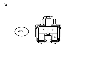
Text in Illustration *a Front view of wire harness connector
(to Stop Light Switch Assembly)
Disconnect the stop light switch assembly connector.
-
Measure the voltage according to the value(s) in the table below.
Standard Voltage Tester Connection Switch Condition Specified Condition A38-2 - Body ground Always 11 to 14 V A38-4 - Body ground Ignition switch ON 11 to 14 V
OK
INSPECT STOP LIGHT SWITCH ASSEMBLY Click here
NG
REPAIR OR REPLACE HARNESS OR CONNECTOR Click here
-
-
CHECK HARNESS AND CONNECTOR (TERMINAL VOLTAGE)
-
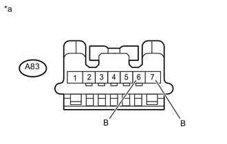
Text in Illustration *a Front view of wire harness connector
(to Stop Light Switch Assembly)
Disconnect the stop light switch assembly connector.
-
Measure the voltage according to the value(s) in the table below.
Standard Voltage Tester Connection Switch Condition Specified Condition A83-7 (B) - Body ground Always 11 to 14 V A83-6 (B) - Body ground Ignition switch ON 11 to 14 V
NG
REPAIR OR REPLACE HARNESS OR CONNECTOR Click here
OK
-
-
INSPECT STOP LIGHT SWITCH ASSEMBLY
-
Inspect the stop light switch assembly (for Bulb Type Stop Light) Click here.
-
Inspect the stop light switch assembly (for LED Type Stop Light) Click here.
NG
REPLACE STOP LIGHT SWITCH ASSEMBLY Click here
OK
-
-
INSPECT ECM (STP AND ST1- VOLTAGE)
-
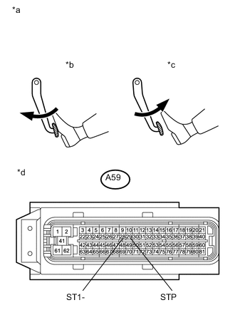
Text in Illustration *a Brake pedal operation *b Brake Pedal Depressed *c Brake Pedal Released *d Front view of harness connector
(to ECM)
Disconnect the ECM connector.
-
Turn the ignition switch to ON.
-
Measure the voltage according to the value(s) in the table below.
Standard Voltage Tester Connection Condition Specified Condition A59-28 (ST1-) - Body ground Released 11 to 14 V Depressed 0 to 3 V A59-29 (STP) - Body ground Released 0 to 3 V Depressed 11 to 14 V
NG
REPAIR OR REPLACE HARNESS OR CONNECTOR Click here
OK
-
-
REPLACE ECM
-
Replace the ECM Click here.
NEXT
CONFIRM WHETHER MALFUNCTION HAS BEEN SUCCESSFULLY REPAIRED Click here
-
-
REPLACE STOP LIGHT SWITCH ASSEMBLY
-
Replace the stop light switch assembly Click here.
NEXT
CONFIRM WHETHER MALFUNCTION HAS BEEN SUCCESSFULLY REPAIRED Click here
-
-
REPAIR OR REPLACE HARNESS OR CONNECTOR
NEXT
-
CONFIRM WHETHER MALFUNCTION HAS BEEN SUCCESSFULLY REPAIRED
-
Connect the intelligent tester to the DLC3.
-
Turn the ignition switch to ON and turn the tester on.
-
Clear the DTCs Click here.
-
Turn the ignition switch to ON.
-
Depress the brake pedal for 10 seconds or more.
-
Enter the following menus: Powertrain / Engine and ECT / DTC / Pending.
-
Confirm that the pending DTC is not output again.
NEXT
END
-