ECD SYSTEM(w/o DPF), Diagnostic DTC:P0502, P0503
| DTC Code | DTC Name |
|---|---|
| P0502 | Vehicle Speed Sensor "A" Circuit Low |
| P0503 | Vehicle Speed Sensor "A" Intermittent / Erratic / High |
DESCRIPTION
Vehicles, which are equipped with ABS (Anti-lock Brake System), detect the vehicle speed using the skid control ECU (brake actuator assembly) and wheel speed sensor. The wheel speed sensor monitors the wheel rotation speed and sends a signal to the skid control ECU (brake actuator assembly). The skid control ECU converts the wheel speed signal into a 4-pulse signal and transmits it to the ECM via the combination meter assembly. The ECM determines the vehicle speed based on the frequency of the pulse signal.
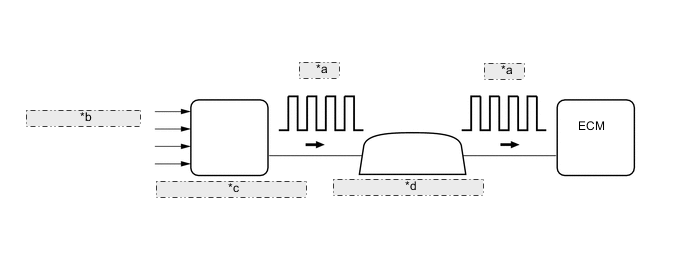
| *a | 4-Pulse |
| *b | from Wheel Speed Sensor |
| *c | Skid Control ECU (Brake Actuator Assembly) |
| *d | Combination Meter Assembly |
| DTC Detection Drive Pattern | DTC Detection Condition | Trouble Area |
|---|---|---|
| Vehicle is driven with engine at high load | No vehicle speed sensor signal to ECM (2 trip detection logic) |
|
| DTC Detection Drive Pattern | DTC Detection Condition | Trouble Area |
|---|---|---|
| Vehicle is driven with engine at high load | Vehicle speed exceeds threshold (2 trip detection logic) |
|
| DTC No. | Data List |
|---|---|
| P0502 | Vehicle Speed |
| P0503 |
WIRING DIAGRAM
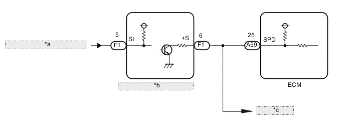
| *a | from Skid Control ECU (Brake Actuator Assembly) |
| *b | Combination Meter Assembly |
| *c | to Other ECUs |
CAUTION / NOTICE / HINT
Note
When replacing the ECM, the ECM needs Registration and Initialization Click here.
Tech Tips
-
When the ECM must be replaced, before replacing the ECM, perform the "Learning Values Save" function using the intelligent tester. Then after installing the new ECM, perform all of the initialization/registrations for the "Learning Values Write" function by following the instructions shown on the tester display.
-
Read freeze frame data using the intelligent tester. Freeze frame data records the engine condition when malfunctions are detected. When troubleshooting, freeze frame data can help determine if the vehicle was moving or stationary, if the engine was warmed up or not, and other data from the time the malfunction occurred.
PROCEDURE
-
READ VALUE USING INTELLIGENT TESTER (VEHICLE SPEED)
-
Connect the intelligent tester to the DLC3.
-
Turn the ignition switch to ON and turn the tester on.
-
Enter the following menus: Powertrain / Engine and ECT / Data List / Vehicle Speed.
-
Drive the vehicle.
-
Read the value displayed on the tester.
OK Vehicle speeds displayed on the tester and the speedometer display are equal.
OK 
CHECK FOR INTERMITTENT PROBLEMS Click here
NG 
-
-
CHECK COMBINATION METER SYSTEM
-
Inspect the circuit that send vehicle speed signals to this system in the meter system Click here.
NEXT
-
-
CHECK WHETHER MALFUNCTION HAS BEEN SUCCESSFULLY REPAIRED
-
Connect the intelligent tester to the DLC3.
-
Turn the ignition switch to ON and turn the tester on.
-
Clear the DTCs Click here.
-
Turn the ignition switch off and wait for 30 seconds or more.
-
Start the engine.
-
Drive the vehicle with the engine at high load and in high gear.
CAUTION:
When performing the confirmation driving pattern, obey all speed limits and traffic laws.
-
Enter the following menus: Powertrain / Engine and ECT / DTC / Pending.
-
Confirm that the pending DTC is not output again.
Tech Tips
If no DTCs (no pending DTCs) are output to the tester, the repair has been successfully completed.
NEXT
END
-