ECD SYSTEM(w/o DPF), Diagnostic DTC:P0234, P0299
| DTC Code | DTC Name |
|---|---|
| P0234 | Turbocharger / Supercharger Overboost Condition |
| P0299 | Turbocharger / Supercharger Underboost |
DESCRIPTION
Refer to DTC P0045 Click here.
| DTC Detection Drive Pattern | DTC Detection Condition | Trouble Area |
|---|---|---|
| All of the following conditions are met:
|
Actual turbocharger pressure is at least 25 kPa higher than target pressure for about 5 seconds (1 trip detection logic) |
|
| DTC Detection Drive Pattern | DTC Detection Condition | Trouble Area |
|---|---|---|
| All of the following conditions are met:
|
Actual turbocharger pressure is at least 25 kPa lower than target pressure for about 5 seconds (1 trip detection logic) |
|
| DTC No. | Data List |
|---|---|
| P0234 P0299 |
|
Tech Tips
-
If DTC P0234 or P0299 is stored, the following symptoms may appear.
-
Poor acceleration
WIRING DIAGRAM
Refer to DTC P0045 Click here.
Refer to DTC P0122 Click here.
Refer to DTC P0236 Click here.
Refer to DTC P0405 Click here.
CAUTION / NOTICE / HINT
Note
When replacing the ECM, the ECM needs Registration and Initialization Click here.
Tech Tips
-
When the ECM must be replaced, before replacing the ECM, perform the "Learning Values Save" function using the intelligent tester. Then after installing the new ECM, perform all of the initialization/registrations for the "Learning Values Write" function by following the instructions shown on the tester display.
-
Read freeze frame data using the intelligent tester. Freeze frame data records the engine condition when malfunctions are detected. When troubleshooting, freeze frame data can help determine if the vehicle was moving or stationary, if the engine was warmed up or not, and other data from the time the malfunction occurred.
PROCEDURE
-
CHECK ANY OTHER DTCS OUTPUT (IN ADDITION TO DTC P0234 AND/OR P0299)
-
Connect the intelligent tester to the DLC3.
-
Turn the ignition switch to ON and turn the tester on.
-
Enter the following menus: Powertrain / Engine and ECT / DTC.
-
Read the DTCs.
Result Result Proceed to DTC P0234 or P0299 A DTC P0234 or P0299 and other DTCs B Tech Tips
If any DTCs other than P0234 or P0299 are output, troubleshoot those DTCs first.
B 
GO TO DTC CHART Click here
A 
-
-
READ VALUE USING INTELLIGENT TESTER (MAP AND TARGET BOOSTER PRESSURE)
-
Connect the intelligent tester to the DLC3.
-
Start the engine and turn the tester on.
-
Enter the following menus: Powertrain / Engine and ECT / Data List / MAP and Target Booster Pressure.
-
Take a snapshot when then engine is idling and the engine speed is maintained at 4500 rpm with no load.
-
Check the condition of the vehicle using the snapshot.
Result Result Proceed to Difference between MAP and Target Booster Pressure is +/-15 kPa or more A Except above B
B 
CHECK WHETHER DTC OUTPUT RECURS (DTC P0234 OR P0299) Click here
A
-
-
CHECK INTAKE SYSTEM
-
Check for air leaks and blockages between the air cleaner case and the turbocharger, and between the turbocharger and the intake manifold.
Result Result Proceed to Leaks and/or blockages exists in the intake system A No leaks and/or blockages in the intake system B Tech Tips
-
Inspect air intake system, especially hoses and pipes between the air cleaner and the turbocharger.
-
Check for abnormal disconnection, pipe and hose squashing, and any damages in the intake system.
-
Using your hand, check whether the pipes and hoses in the intake system are securely connected.
-
By applying soapy water and revving the engine, air leaks from the intake system can be checked by checking for bubbles.
-
Check for any modifications in the intake system made by the user.
-
B
INSPECT TURBOCHARGER SUB-ASSEMBLY Click here
A
-
-
REPAIR OR REPLACE INTAKE SYSTEM
-
Repair or replace the malfunctioning parts of the intake system.
NEXT
CHECK WHETHER DTC OUTPUT RECURS (DTC P0234 OR P0299) Click here
-
-
INSPECT TURBOCHARGER SUB-ASSEMBLY
-
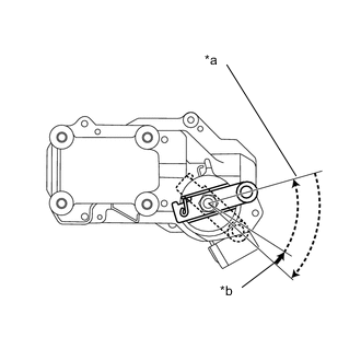
Text in Illustration *a Idling to ignition switch off *b Ignition switch ON to idling Check the motor movement when turning the ignition switch to ON, when starting the engine, and then when turning the ignition switch off.
OK Motor moves smoothly as shown in the illustration.
OK
READ VALUE USING INTELLIGENT TESTER (MAP AND ATMOSPHERE PRESSURE) Click here
NG
INSPECT TURBOCHARGER SUB-ASSEMBLY (DC MOTOR) Click here
-
-
CHECK WHETHER DTC OUTPUT RECURS (DTC P0234 OR P0299)
-
Connect the intelligent tester to the DLC3.
-
Turn the ignition switch to ON and turn the tester on.
-
Clear the DTCs Click here.
-
Turn the ignition switch off.
-
Turn the ignition switch to ON.
-
Turn the ignition switch off and wait for 30 seconds or more.
-
Turn the ignition switch to ON and wait for 10 seconds or more.
-
Start the engine and warm it up until the engine coolant temperature sensor reaches 75°C (167°F) or more.
-
Drive the vehicle at steady speed driving with a high engine load (at an engine speed of 3000 rpm or more).
CAUTION:
When performing the confirmation driving pattern, obey all speed limits and traffic laws.
Tech Tips
Altitude should be below 1000 m from sea level.
-
Enter the following menus: Powertrain / Engine and ECT / DTC.
-
Read the DTCs.
Result Result Proceed to No DTC output A DTC P0234 or P0299 B
A
CHECK FOR INTERMITTENT PROBLEMS Click here
B
-
-
INSPECT TURBOCHARGER SUB-ASSEMBLY (DC MOTOR)
-
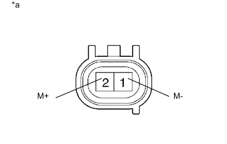
Text in Illustration *a Component without harness connected
(DC Motor)
Disconnect the DC motor connector.
-
Measure the resistance according to the value(s) in the table below.
Standard Resistance Tester Connection Condition Specified Condition 1 (M-) - 2 (M+) Always 0.3 to 100 Ω
NG
REPLACE TURBOCHARGER SUB-ASSEMBLY Click here
OK
-
-
CHECK HARNESS AND CONNECTOR (DC MOTOR - ECM)
-
Disconnect the DC motor connector.
-
Disconnect the ECM connector.
-
Measure the resistance according to the value(s) in the table below.
Standard Resistance Tester Connection Condition Specified Condition B54-2 (M+) - B21-34 (M+) Always Below 1 Ω B54-1 (M-) - B21-33 (M-) Always Below 1 Ω B54-2 (M+) or B21-34 (M+) - Body ground Always 10 kΩ or higher B54-1 (M-) or B21-33 (M-) - Body ground Always 10 kΩ or higher
NG
REPAIR OR REPLACE HARNESS OR CONNECTOR Click here
OK
-
-
READ VALUE USING INTELLIGENT TESTER (MAP AND ATMOSPHERE PRESSURE)
-
Connect the intelligent tester to the DLC3.
-
Turn the ignition switch to ON and turn the tester on.
-
Enter the following menus: Powertrain / Engine and ECT / Data List / MAP and Atmosphere Pressure.
-
Compare the values when the ignition switch is ON.
Standard Difference between the MAP and the Atmosphere Pressure is less than 7 kPa. Tech Tips
Standard atmospheric pressure is 101 kPa. For every 100 m increase in altitude, pressure drops by 1 kPa. Varies by weather.
OK
PERFORM ACTIVE TEST USING INTELLIGENT TESTER (DIESEL THROTTLE TARGET ANGLE) Click here
NG
-
-
CHECK HARNESS AND CONNECTOR (DIESEL TURBO PRESSURE SENSOR - ECM)
-
Disconnect the diesel turbo pressure sensor connector.
-
Disconnect the ECM connector.
-
Measure the resistance according to the value(s) in the table below.
Standard Resistance Tester Connection Condition Specified Condition B49-2 (PIM) - A59-13 (PIM) Always Below 1 Ω B49-3 (VC) - A59-14 (VPIM) Always Below 1 Ω B49-1 (E) - A59-15 (EPIM) Always Below 1 Ω B49-2 (PIM) or A59-13 (PIM) - Body ground Always 10 kΩ or higher B49-3 (VC) or A59-14 (VPIM) - Body ground Always 10 kΩ or higher B49-1 (E) or A59-15 (EPIM) - Body ground Always 10 kΩ or higher
OK
REPLACE DIESEL TURBO PRESSURE SENSOR Click here
NG
REPAIR OR REPLACE HARNESS OR CONNECTOR Click here
-
-
PERFORM ACTIVE TEST USING INTELLIGENT TESTER (DIESEL THROTTLE TARGET ANGLE)
-
Connect the intelligent tester to the DLC3.
-
Turn the ignition switch to ON and turn the tester on.
-
Enter the following menus: Powertrain / Engine and ECT / Active Test / Diesel Throttle Target Angle.
-
When changing the Active Test value from 0 to 90%, check that Actual Throttle Position smoothly changes to the set opening angle.
Standard value Value smoothly changes to the set opening angle.
OK
PERFORM ACTIVE TEST USING INTELLIGENT TESTER (CONTROL THE EGR STEP POSITION) Click here
NG
-
-
CHECK HARNESS AND CONNECTOR (DIESEL THROTTLE BODY ASSEMBLY - ECM)
-
Disconnect the diesel throttle body assembly connector.
-
Disconnect the ECM connector.
-
Measure the resistance according to the value(s) in the table below.
Standard Resistance Tester Connection Condition Specified Condition A59-43 (M+) - B29-2 (M+) Always Below 1 Ω A59-42 (M-) - B29-1 (M-) Always Below 1 Ω A59-43 (M+) or B29-2 (M+) - Body ground Always 10 kΩ or higher A59-42 (M-) or B29-1 (M-) - Body ground Always 10 kΩ or higher
OK
REPLACE DIESEL THROTTLE BODY ASSEMBLY Click here
NG
REPAIR OR REPLACE HARNESS OR CONNECTOR Click here
-
-
PERFORM ACTIVE TEST USING INTELLIGENT TESTER (CONTROL THE EGR STEP POSITION)
-
Connect the intelligent tester to the DLC3.
-
Turn the ignition switch to ON and turn the tester on.
-
Enter the following menus: Powertrain / Engine and ECT / Active Test / Control the EGR Step Position.
-
When changing the Active Test value from 0 to 100%, check that Actual EGR Valve Pos. smoothly changes to the set opening angle.
OK Value smoothly changes to the set opening angle.
OK
INSPECT ELECTRIC EGR CONTROL VALVE ASSEMBLY Click here
NG
-
-
CHECK HARNESS AND CONNECTOR (ELECTRIC EGR CONTROL VALVE ASSEMBLY - ECM)
-
Disconnect the electric EGR control valve assembly connector.
-
Disconnect the ECM connector.
-
Measure the resistance according to the value(s) in the table below.
Standard Resistance Tester Connection Condition Specified Condition B21-23 (EGM+) - B55-1 (M+) Always Below 1 Ω B21-22 (EGM-) - B55-2 (M-) Always Below 1 Ω B21-23 (EGM+) or B55-1 (M+) - Body ground Always 10 kΩ or higher B21-22 (EGM-) or B55-2 (M-) - Body ground Always 10 kΩ or higher
NG
REPAIR OR REPLACE HARNESS OR CONNECTOR Click here
OK
-
-
INSPECT ELECTRIC EGR CONTROL VALVE ASSEMBLY
-
Remove the electric EGR control valve assembly.
-
Visually check the electric EGR control valve assembly for deposits. If there are deposits, clean the electric EGR control valve assembly.
Note
-
When cleaning the electric EGR control valve assembly, make sure the valve is completely closed.
-
Do not forcibly open the valve, as it may be damaged or deformed.
-
When cleaning the electric EGR control valve assembly, use a piece of cloth soaked with cleaning solvent. Spraying the solvent directly onto these parts or soaking the parts in the solvent may damage the parts.
-
-
Hold the electric EGR control valve assembly up to a light, and then from the side indicated by the arrow in the illustration, visually check that there is no clearance between the valve and body.
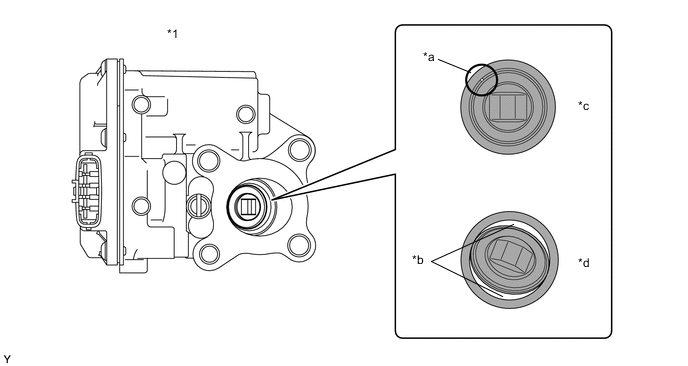
Text in Illustration *1 Electric EGR Control Valve Assembly - - *a Part A *b Clearance *c OK *d NG OK No light passes through (there is no clearance between the valve and body). If light passes through (there is a clearance between the valve and body), replace the electric EGR control valve assembly.
Tech Tips
Light passes through part A shown in the illustration even if the valve is completely closed, this is not a problem.
NG
REPLACE ELECTRIC EGR CONTROL VALVE ASSEMBLY Click here
OK
-
-
CHECK FOR DEPOSIT (EGR PASSAGE)
-
Check the deposit in the EGR passage.
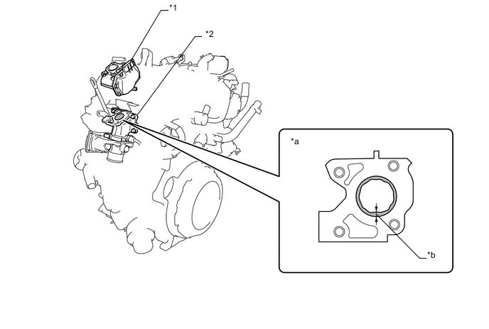
Text in Illustration *1 Electric EGR Control Valve Assembly *2 Intake Air Connector *a EGR Passage of Intake Air Connector *b Carbon Deposit Thickness OK No deposit.
NG
REMOVE DEPOSIT (CLEAN EGR PASSAGE) Click here
OK
-
-
CHECK EXHAUST GAS LEAK
-
Check for exhaust gas leak.
OK No exhaust gas leak.
OK
CHECK WHETHER DTC OUTPUT RECURS (DTC P0234 OR P0299) Click here
NG
REPAIR OR REPLACE MALFUNCTIONING PARTS, COMPONENT AND AREA Click here
-
-
REPLACE TURBOCHARGER SUB-ASSEMBLY
-
Replace the turbocharger sub-assembly Click here.
-
Turn the ignition switch to ON.
-
Turn the ignition switch off and wait for 30 seconds or more.
NEXT
CHECK WHETHER DTC OUTPUT RECURS (DTC P0234 OR P0299) Click here
-
-
REPLACE DIESEL TURBO PRESSURE SENSOR
-
Replace the diesel turbo pressure sensor Click here.
NEXT
CHECK WHETHER DTC OUTPUT RECURS (DTC P0234 OR P0299) Click here
-
-
REPLACE ELECTRIC EGR CONTROL VALVE ASSEMBLY
-
Replace the electric EGR control valve assembly Click here.
-
Turn the ignition switch to ON.
-
Turn the ignition switch off and wait for 30 seconds or more.
NEXT
CHECK WHETHER DTC OUTPUT RECURS (DTC P0234 OR P0299) Click here
-
-
REPLACE DIESEL THROTTLE BODY ASSEMBLY
-
Replace the diesel throttle body assembly Click here.
-
Turn the ignition switch to ON.
-
Turn the ignition switch off and wait for 30 seconds or more.
NEXT
CHECK WHETHER DTC OUTPUT RECURS (DTC P0234 OR P0299) Click here
-
-
REPAIR OR REPLACE HARNESS OR CONNECTOR
NEXT
CHECK WHETHER DTC OUTPUT RECURS (DTC P0234 OR P0299) Click here
-
REMOVE DEPOSIT (CLEAN EGR PASSAGE)
-
Remove the electric EGR control valve assembly, diesel throttle body assembly, intake air connector, EGR pipe connector, EGR with cooler pipe assembly and No. 2 EGR valve assembly.
-
Remove the deposits from those parts and clean them.
Note
-
When cleaning the electric EGR control valve assembly and the diesel throttle body assembly, use a piece of cloth. Spraying the solvent directly onto these parts or soaking the parts in the solvent may damage the parts.
-
Extreme care must be taken to prevent the removed deposits from falling into the engine unit during cleaning.
Tech Tips
-
Remove the intake manifold from the cylinder head when it has to be cleaned.
-
Do not leave any deposits in the electric EGR control valve assembly when cleaning the valve.
-
NEXT
CHECK WHETHER DTC OUTPUT RECURS (DTC P0234 OR P0299) Click here
-
-
REPAIR OR REPLACE MALFUNCTIONING PARTS, COMPONENT AND AREA
NEXT
-
CHECK WHETHER DTC OUTPUT RECURS (DTC P0234 OR P0299)
-
Connect the intelligent tester to the DLC3.
-
Turn the ignition switch to ON and turn the tester on.
-
Clear the DTCs Click here.
-
Turn the ignition switch off.
-
Turn the ignition switch to ON.
-
Turn the ignition switch off and wait for 30 seconds or more.
-
Turn the ignition switch to ON and wait for 10 seconds or more.
-
Start the engine and warm it up until the engine coolant temperature sensor reaches 75°C (167°F) or more. (A)
-
Drive the vehicle at steady speed driving with a high engine load (at an engine speed of 3000 rpm or more). (B)
CAUTION:
When performing the confirmation driving pattern, obey all speed limits and traffic laws.
Tech Tips
Altitude should be below 1000 m from sea level.
-
Enter the following menus: Powertrain / Engine and ECT / DTC.
-
Read the DTCs.
Tech Tips
Perform the following procedure using the tester to determine whether or not the DTC judgment has been carried out.
-
Enter the following menus: Powertrain / Engine and ECT / Utility / All Readiness.
-
Input DTC P0234 or P0299.
-
Check that STATUS is NORMAL. If STATUS is INCOMPLETE or N/A, repeat the (A) and (B) driving pattern process.
Result Result Proceed to ABNORMAL A NORMAL B
-
B
END
A
-
-
REPLACE ECM
-
Replace the ECM Click here.
NEXT
-
-
CONFIRM WHETHER MALFUNCTION HAS BEEN SUCCESSFULLY REPAIRED
-
Connect the intelligent tester to the DLC3.
-
Turn the ignition switch to ON and turn the tester on.
-
Clear the DTCs Click here.
-
Turn the ignition switch off.
-
Turn the ignition switch to ON.
-
Turn the ignition switch off and wait for 30 seconds or more.
-
Turn the ignition switch to ON and wait for 10 seconds or more.
-
Start the engine and warm it up until the engine coolant temperature sensor reaches 75°C (167°F) or more. (A)
-
Drive the vehicle at steady speed driving with a high engine load (at an engine speed of 3000 rpm or more). (B)
CAUTION:
When performing the confirmation driving pattern, obey all speed limits and traffic laws.
Tech Tips
Altitude should be below 1000 m from sea level.
-
Enter the following menus: Powertrain / Engine and ECT / DTC.
-
Confirm that the DTC is not output again.
Tech Tips
Perform the following procedure using the tester to determine whether or not the DTC judgment has been carried out.
-
Enter the following menus: Powertrain / Engine and ECT / Utility / All Readiness.
-
Input DTC P0234 or P0299.
-
Check that STATUS is NORMAL. If STATUS is INCOMPLETE or N/A, repeat the (A) and (B) driving pattern process.
-
NEXT
END
-