ECD SYSTEM(w/o DPF) SYSTEM DESCRIPTION
-
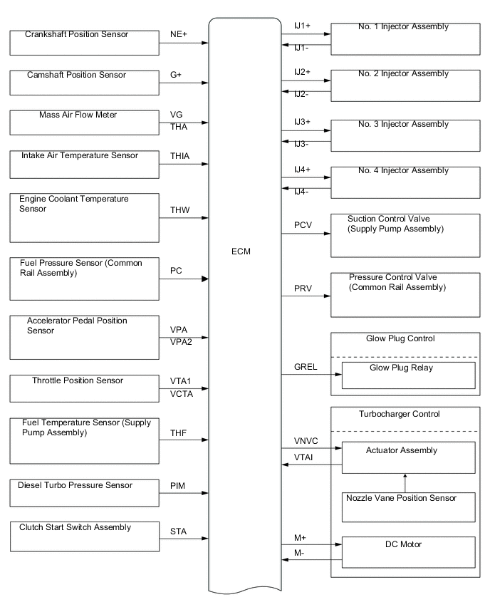
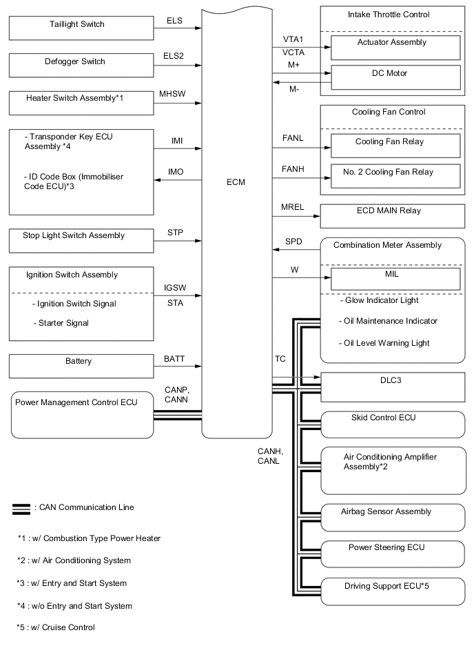
ENGINE CONTROL SYSTEM
-
System Control Table
-
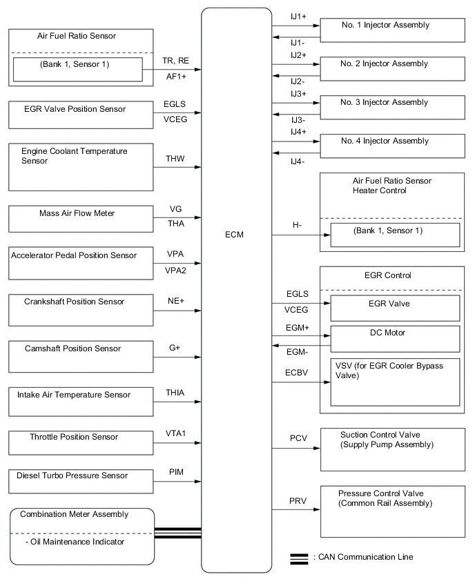
The engine control system of the 1ND-TV engine has the following systems.
System Description Fuel injection volume control Based on the signals received from the various sensors, the ECM determines the fuel injection volume in accordance with the engine condition. Fuel injection timing control Based on the signals received from the various sensors, the ECM determines the fuel injection timing in accordance with the engine condition. Fuel pressure control Based on the signals received from the various sensors, the ECM determines the fuel pressure via the suction control valve and pressure control valve in accordance with the engine condition. Idle speed control The ECM determines the idle speed in accordance with the engine condition, and controls the fuel injection volume in order to maintain the target idle speed. Pilot injection control Based on the signals received from the various sensors, the ECM determines pilot injection volume, timing, and interval (between pilot injection and main injection) in accordance with the engine condition. Glow plug control Controls the length of time when the current is applied to the glow plug assemblies, in accordance with the engine coolant temperature. Turbocharger control Based on signals from the various sensors, the ECM controls the turbocharger in accordance with engine condition by adjusting the nozzle vane. Intake throttle control Based on the signals received from the various sensors, the ECM determines throttle position in accordance with engine condition. Fully closes the diesel throttle control valve in order to reduce the vibration when the engine is stopped.
-
-
Fuel Injection Volume Control
-
Fuel injection volume has two values, "Final Injection Volume", "Starting Injection Volume".
Final injection volume The ECM compares the basic and maximum injection volumes, and determines the smaller calculated value to be the final injection volume. The ECM reduces injection volume to ensure drivability when the clutch switch is ON (the clutch pedal is depressed). Starting injection volume The starting injection volume is determined in accordance with the crankshaft position sensor signal (cranking time) and engine coolant temperature sensor signal. When the engine is cold, the engine coolant temperature will be lower and the injection volume will be greater.
-
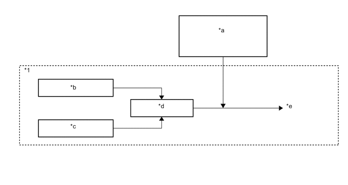
Basic Injection Volume:
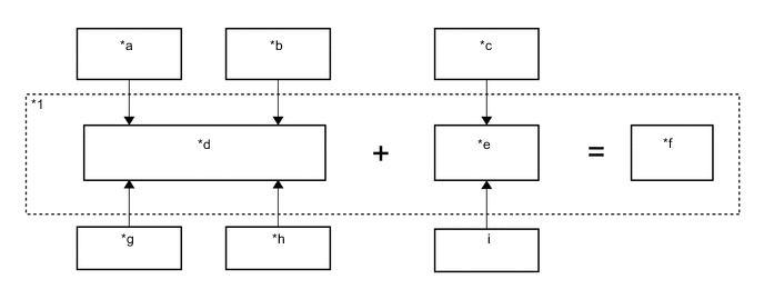
Text in Illustration *1 ECM - - *a Engine Coolant Temperature Sensor *b Crankshaft Position Sensor (Engine Speed) *c Clutch Start Switch *d Calculation of Basic Injection Volume *e Basic Injection Volume Correction *f Basic Injection Volume *g ISC Correction *h Accelerator Pedal Position Sensor *i Vehicle Speed Signal - - -
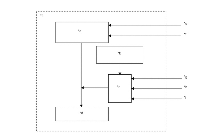
Maximum Injection Volume:
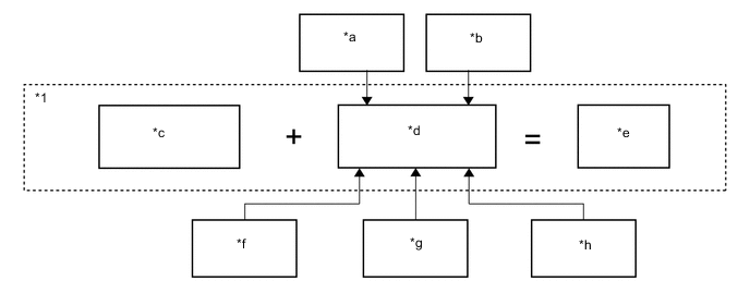
Text in Illustration *1 ECM - - *a Engine Coolant Temperature Sensor *b Crankshaft Position Sensor (Engine Speed) *c Basic/Maximum Injection Volume (Map data inside of ECM) *d Maximum Injection Volume Correction *e Maximum Injection Volume *f Diesel Turbo Pressure Sensor *g Mass Air Flow Meter *h Atmospheric Pressure Sensor -
Final Injection Volume:
Text in Illustration *1 ECM - - *a Fuel Pressure Sensor (Common Rail Assembly) *b Basic Injection Volume *c Maximum Injection Volume *d Comparison* *e Final Injection Volume - - *: Selects lower injection volume
-
-
-
Fuel Injection Timing Control
-
Fuel injection timing is controlled as shown below.
Text in Illustration *1 ECM - - *a Basic Injection Timing *b Atmospheric Pressure Sensor *c Correction *d Injection Timing *e Final Injection Volume *f Crankshaft Position Sensor (Engine Speed) *g Intake Air Temperature Sensor *h Engine Coolant Temperature Sensor *i Diesel Turbo Pressure Sensor - -
-
-
Fuel Pressure Control
-
The ECM calculates the target injection pressure (30000 to 160000 kPa) based on the final injection volume and signals from the crankshaft position sensor.
-
To control fuel pressure, signals sent to suction control valve of the supply pump assembly regulate the pumping volume and signals sent to pressure control valve of the common-rail regulate the discharge volume, so that the pressure detected by the fuel pressure sensor matches the target injection pressure.
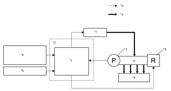
Text in Illustration *1 Suction Control Valve (Supply Pump Assembly) *2 ECM *3 Fuel Pressure Sensor (Common Rail Assembly) *4 Pressure Control Valve (Common Rail Assembly) *5 Common Rail Assembly *6 Injector assembly *a Crankshaft Position Sensor (Engine speed) *b Final Injection Volume *c Calculation of Target Injection Pressure *d Electric Signal Supply Pump *e Fuel Pressure - - Suction control valve control The ECM controls the suction control valve opening in order to regulate the fuel volume that is pumped by the supply pump to the common-rail. Consequently, the fuel pressure in the common-rail is controlled to the target injection pressure. Suction control valve opening small When the suction control valve opening is small, the fuel suction area is kept small, which decreases the transferable fuel quantity. The plunger strokes fully, however, the suction volume becomes small due to the small suction area. Pumping will start at the time when the fuel pressure has become higher than the common-rail pressure. Suction control valve opening large When the suction control valve opening is large, the fuel suction area is kept large, which increases the transferable fuel quantity. The plunger strokes fully, the suction volume will increase because the suction area is large. Pumping will start at the time when the fuel pressure has become higher than the common-rail pressure.
-
Suction Control Valve Opening Small:
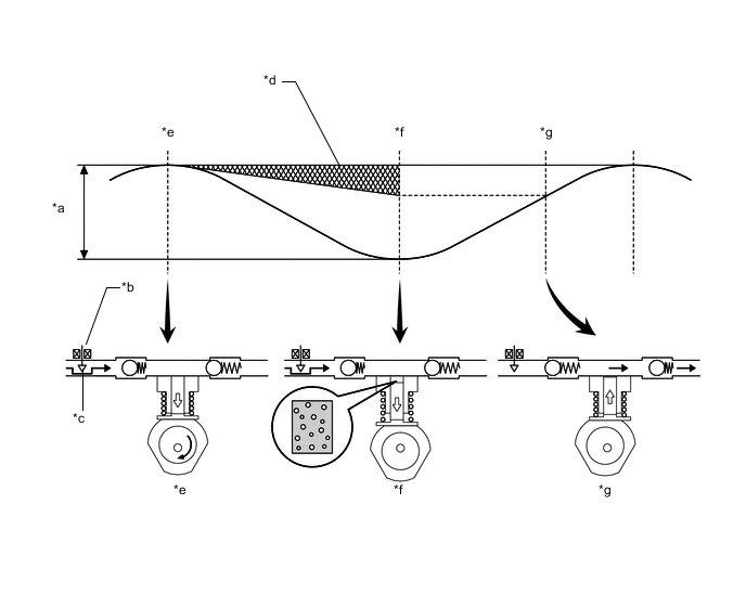
Text in Illustration *a Cam Stroke *b Suction Control Valve *c Small Suction Area *d Fuel Pumping Mass *e Plunger Top-dead-center *f Plunger Bottom-dead-center *g Pumping Starting Point - - -
Suction Control Valve Opening Large:
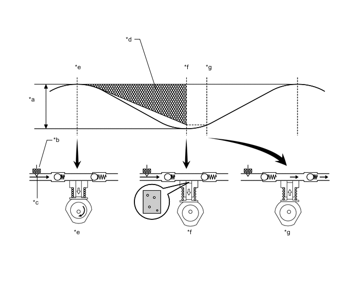
Text in Illustration *a Cam Stroke *b Suction Control Valve *c Large Suction Area *d Fuel Pumping Mass *e Plunger Top-dead-center *f Plunger Bottom-dead-center *g Pumping Starting Point - -
-
-
-
Idle Speed Control
-
ISC correction is controlled as shown below.
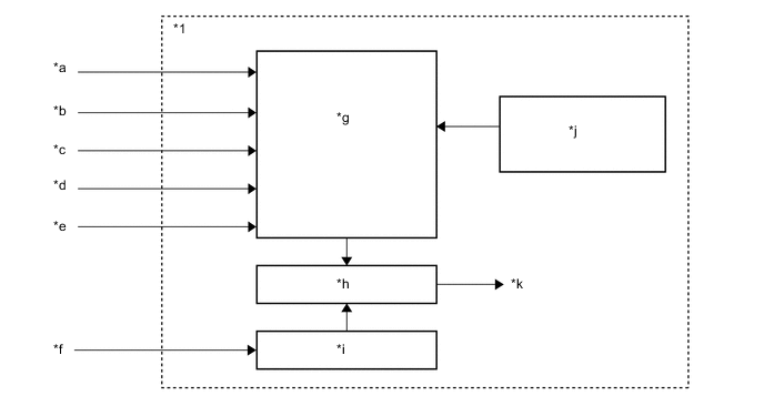
Text in Illustration *1 ECM - - *a Engine Coolant Temperature Sensor *b Vehicle Speed Sensor *c A/C Switch Signal (w/ Air Conditioning System) *d Power Heater Signal (w/ Combustion Type Power Heater) *e PTC Heater Signal (w/ PTC Heater) *f Crankshaft Position Sensor *g Target Speed Calculation *h Comparison *i Actual Engine Speed *j Atmospheric Pressure Sensor *k ISC Correction - -
-
-
Pilot Injection Control
-
Pilot injection is a method that provides an auxiliary fuel injection before the main fuel injection takes place. The purpose of pilot injection is to gently start the combustion of the fuel of the main injection in order to reduce combustion noise.
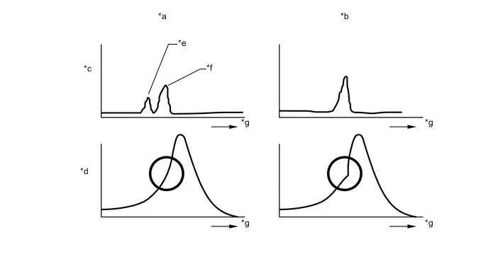
Text in Illustration *a w/ Pilot Injection Control *b w/o Pilot Injection Control *c Fuel Injection *b Combustion Pressure *e Pilot Injection *f Main Injection *g Time - - -
During pilot injection, the pilot injection volume, timing, and interval (between pilot injection and main injection) are controlled as shown below.
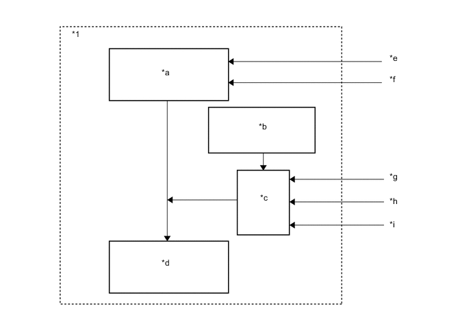
Text in Illustration *1 ECM - - *a Basic Pilot Injection (Volume, Timing, Interval) *b Atmospheric Pressure Sensor *c Correction *d Pilot Injection (Volume, Timing, Interval) *e Final Injection Volume *f Crankshaft Position Sensor (Engine Speed) *g Atmospheric Temperature Sensor *h Engine Coolant Temperature Sensor *i Diesel Turbo Pressure Sensor - -
-
-
Turbocharger Control
-
The ECM controls the nozzle vane position, in order to obtain the calculated target turbo pressure appropriate to the engine operating condition.
-
The ECM calculates the optimal nozzle vane position in accordance with the driving conditions (engine speed, injection volume, atmospheric pressure, and engine coolant temperature etc). The ECM controls the nozzle vane position in accordance with the target nozzle vane position calculated by the ECM and the actual nozzle vane position signal provided by the nozzle vane position sensor.
Text in Illustration *1 DC Motor *2 Nozzle Vane Position Sensor *3 Diesel Turbo Pressure Sensor *4 ECM *a Target Nozzle Vane Position Signal *b Actual Nozzle Vane Position Signal *c Atmospheric Pressure Sensor *d Crankshaft Position Sensor *e Injection Volume *f Engine Coolant Temperature Sensor *g Atmospheric Temperature Sensor - -
-
-
-
EMISSION CONTROL SYSTEM
-
System Control Table
-
The emission control system of the 1ND-TV engine has the following systems.
System Description EGR Control Based on the signals received from the sensors, the ECM determines the EGR volume via EGR valve and throttle valve in accordance with the engine condition. Air fuel Ratio Sensor Heater Control Maintains the temperature of the air fuel ratio sensors at an appropriate level to increase accuracy of detection of the oxygen concentration in the exhaust gas.
-
-
EGR Control
-
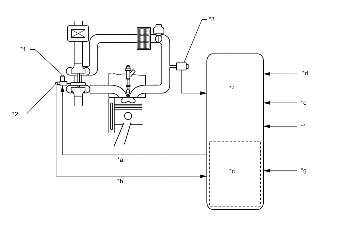
This system is designed to reduce and control NOx formation due to a reduction of peak temperature in the engine combustion chamber, which is accomplished by introducing an exhaust gas into the intake manifold.
-
By sensing the engine driving conditions and actual amount of the EGR valve opening, the ECM operates the EGR valve and diesel throttle control motor, and regulates the amount of exhaust gas.
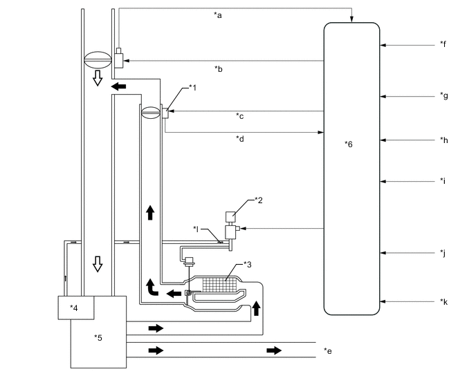
Text in Illustration *1 Electric EGR Control Valve Assembly *2 VSV (for EGR Cooler Bypass Switching Valve) *3 EGR Cooler *4 Vacuum Pump *5 Engine *6 ECM *a Throttle Position Sensor Signal *b Throttle Valve Control *c EGR Valve Control *d EGR Valve Position Signal *e to Turbocharger *f Accelerator Pedal Position Sensor *g Crankshaft Position Sensor *h Mass Air Flow Meter *i Engine Coolant Temperature Sensor *j Intake Air Temperature Sensor *k Diesel Turbo Pressure Sensor *l Vacuum 
Exhaust Gas 
Intake Air
-
-
-
FUEL SYSTEM
-
Fuel System Description
-
A common-rail system manufactured by BOSCH is used in the fuel injection system. In this system, the highly pressurized fuel that is supplied by the supply pump is stored in the common rail, and ECM sends signals to the injector assemblies in order to control the injection timing and injection volume.
-
A piezo type injector assembly is used to precisely control the fuel injection volume and timing.
-
The quick connectors are used to connect the fuel pipe with the fuel hose for excellent serviceability.
-
A fuel filter with a fuel heater is used.
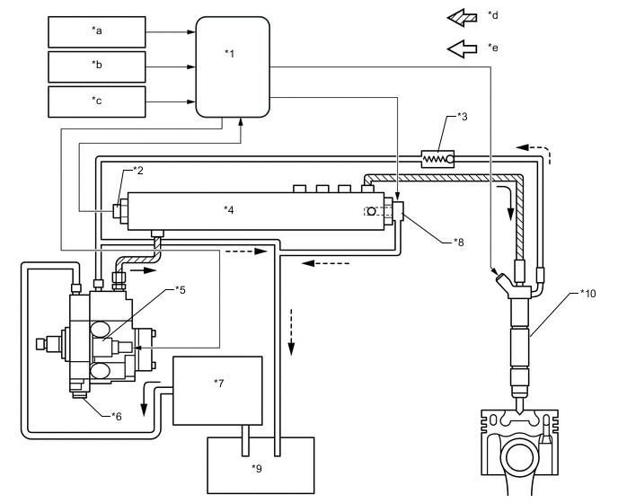
Text in Illustration *1 ECM *2 Fuel Pressure Sensor (Common Rail Assembly) *3 Check Valve *4 Common Rail Assembly *5 Suction Control Valve *6 Supply Pump Assembly *7 Fuel Filter with Heater *8 Pressure Control Valve (Common Rail Assembly) *9 Fuel Tank *10 Injector Assembly *a NE Signal *b G Signal *c Various Signal *d High Pressure Fuel *e Low Pressure Fuel - -
-
-
Supply Pump
-
Due to the rotation of the inner cam (eccentric cam), the outer cam pushes plunger "A" upward as illustrated below. The force of the spring pulls plunger "C". As a result, plunger "C" draws fuel in, and plunger "A" pumps fuel at the same time.
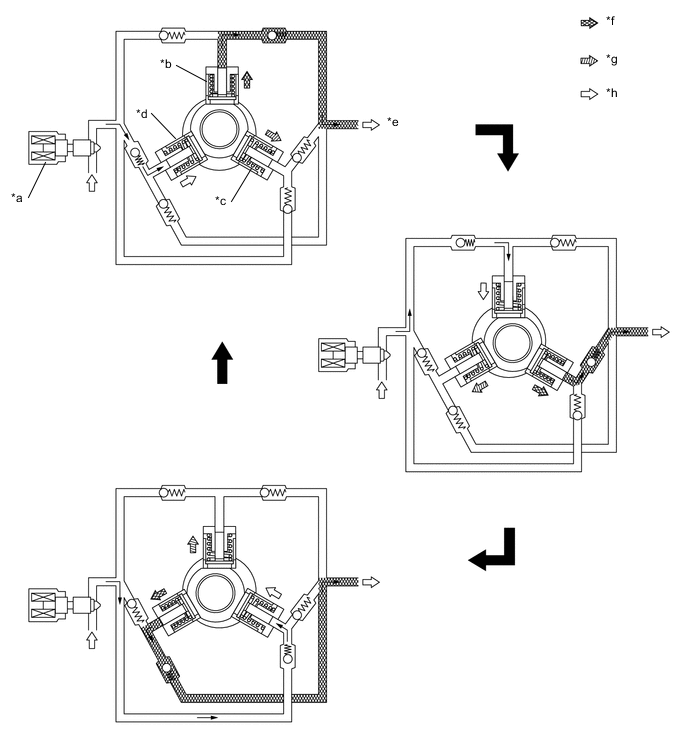
Text in Illustration *a Suction Control Valve *b Plunger A *c Plunger B *d Plunger C *e to Common-rail *f Pumping Finish *g Pumping Start *h Suction
-
-
Injector Assembly : Needle Opening (During Injection)
-
The actuator is activated.
-
Valve bolt opens (moves downwards) due to actuator lift.
-
Pressure of nozzle needle tip decreases.
-
Nozzle needle opens (moves upwards).
-
-
Injector Assembly : Needle Closing (While Stopped)
-
The actuator is deactivated.
-
Valve bolt closes (moves upwards) due to the valve spring.
-
Pressure of nozzle needle tip increases.
-
Nozzle needle closes (moves downwards).
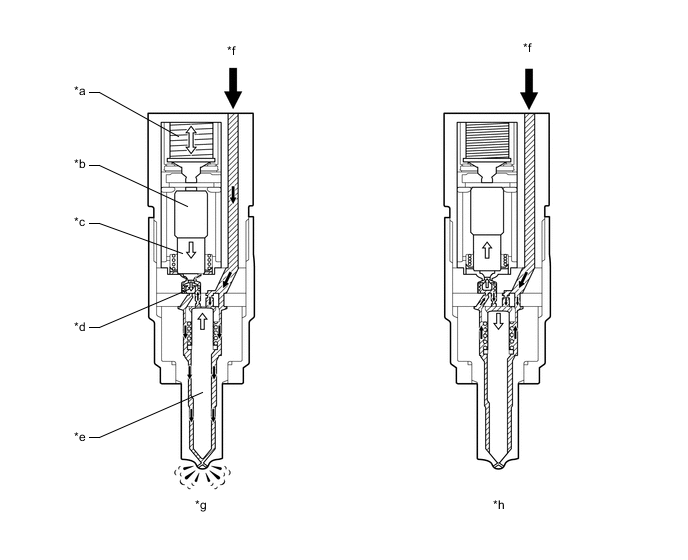
Text in Illustration *a Piezo Actuator *b Amplifier Piston *c Valve Piston *d Valve Bolt *e Nozzle Needle *f Fuel *g During Injection *h While Stopped
-
-