ECD SYSTEM(w/ DPF) VC Output Circuit
DESCRIPTION
The ECM constantly generates 5 V of power from the battery voltage supplied to the +B, +B2 and +B3 (BATT) terminal to operate the microprocessor. The ECM also provides this power to the sensors through the VC output circuit.
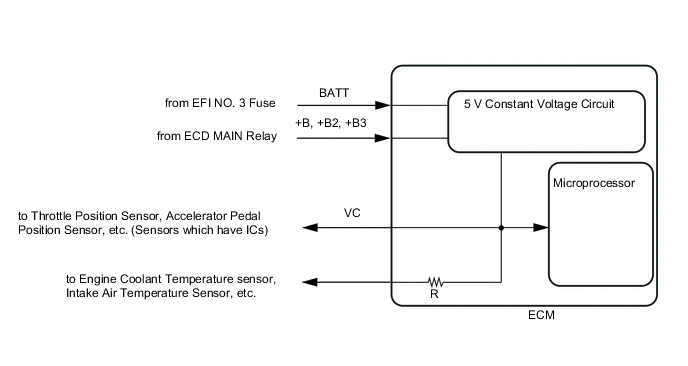
When the VC circuit is short-circuited, the microprocessor in the ECM and sensors that are supplied with power through the VC circuit are inactivated because the power is not supplied from the VC circuit. Under this condition, the system does not start up and the MIL does not illuminate even if the system malfunctions.
Tech Tips
Under normal conditions, the MIL is illuminated for several seconds when the ignition switch is first turned to ON. The MIL turns off when the engine is started.
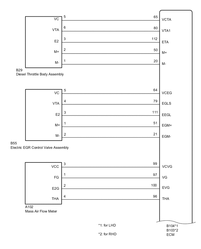
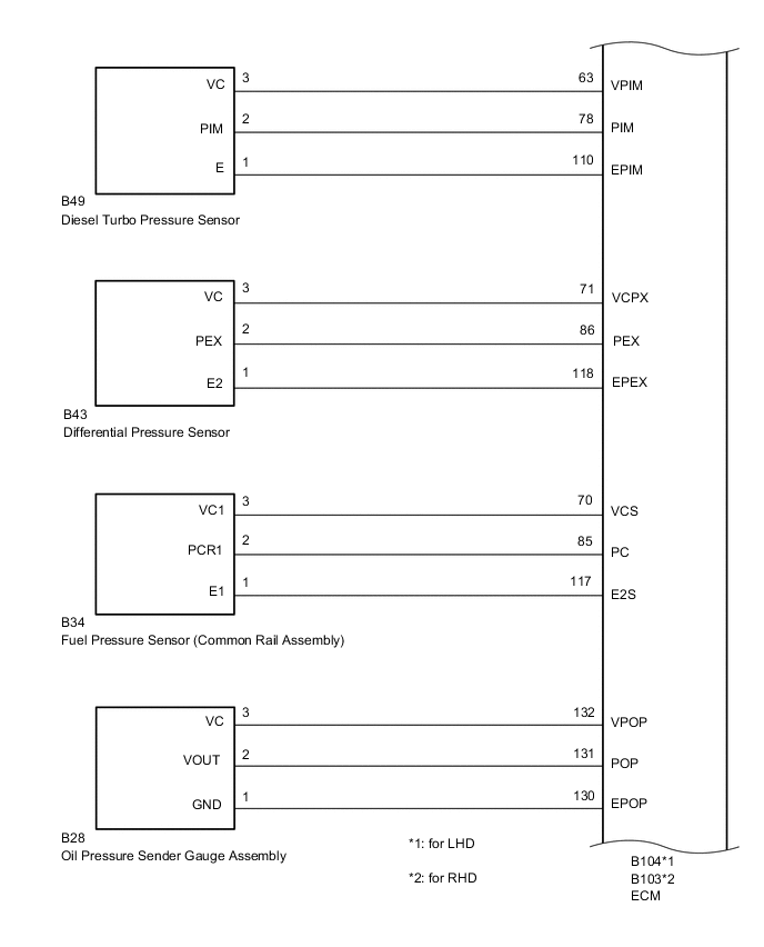
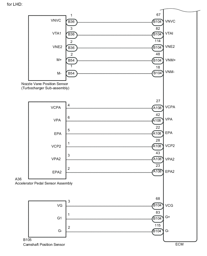
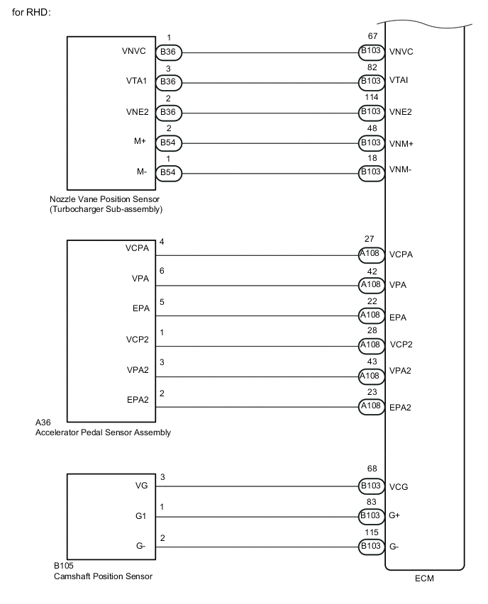
WIRING DIAGRAM
CAUTION / NOTICE / HINT
CAUTION:
When replacing the ECM, the ECM needs Registration and Initialization Click here.
Tech Tips
-
When the ECM must be replaced, before replacing the ECM, perform the "Learning Values Save" function using the GTS. Then after installing the new ECM, perform all of the initialization/registrations for the "Learning Values Write" function by following the instructions shown on the GTS display.
PROCEDURE
-
CHECK MIL
-
Check that the Malfunction Indicator Lamp (MIL) lights up when turning the ignition switch to ON.
Result Result Proceed to MIL does not illuminate A MIL illuminates B
B 
PROCEED TO NEXT SUSPECTED AREA SHOWN IN PROBLEM SYMPTOMS TABLE Click here
A 
-
-
CHECK COMMUNICATION BETWEEN GTS AND ECM
-
Connect the GTS to the DLC3.
-
Turn the ignition switch to ON.
-
Turn the GTS on.
-
Check the communication between the GTS and ECM.
Result Result Proceed to Communication is not possible A Communication is possible B
B
GO TO MIL CIRCUIT Click here
A
-
-
CHECK MIL (THROTTLE POSITION SENSOR)
-
Disconnect the B29 diesel throttle body assembly connector.
-
Turn the ignition switch to ON.
-
Check the MIL.
Result Result Proceed to MIL does not illuminate A MIL illuminates B
B
REPLACE DIESEL THROTTLE BODY ASSEMBLY Click here
A
-
-
CHECK MIL (ELECTRIC EGR CONTROL VALVE ASSEMBLY)
-
Disconnect the B55 electric EGR control valve assembly connector.
-
Turn the ignition switch to ON.
-
Check the MIL.
Result Result Proceed to MIL does not illuminate A MIL illuminates B
B
REPLACE ELECTRIC EGR CONTROL VALVE ASSEMBLY Click here
A
-
-
CHECK MIL (ACCELERATOR PEDAL SENSOR ASSEMBLY)
-
Disconnect the A36 accelerator pedal sensor connector.
-
Turn the ignition switch to ON.
-
Check the MIL.
Result Result Proceed to MIL does not illuminate A MIL illuminates B
B
REPLACE ACCELERATOR PEDAL SENSOR ASSEMBLY Click here
A
-
-
CHECK MIL (DIESEL TURBO PRESSURE SENSOR)
-
Disconnect the B49 diesel turbo pressure sensor connector.
-
Turn the ignition switch to ON.
-
Check the MIL.
Result Result Proceed to MIL does not illuminate A MIL illuminates B
B
REPLACE DIESEL TURBO PRESSURE SENSOR Click here
A
-
-
CHECK MIL (NOZZLE VANE POSITION SENSOR (TURBOCHARGER SUB-ASSEMBLY))
-
Disconnect the B36 nozzle vane position sensor connector.
-
Turn the ignition switch to ON.
-
Check the MIL.
Result Result Proceed to MIL does not illuminate A MIL illuminates B
B
REPLACE TURBOCHARGER SUB-ASSEMBLY (NOZZLE VANE POSITION SENSOR) Click here
A
-
-
CHECK MIL (DIFFERENTIAL PRESSURE SENSOR)
-
Disconnect the B43 differential pressure sensor connector.
-
Turn the ignition switch to ON.
-
Check the MIL.
Result Result Proceed to MIL does not illuminate A MIL illuminates B
B
REPLACE DIFFERENTIAL PRESSURE SENSOR Click here
A
-
-
CHECK MIL (FUEL PRESSURE SENSOR (COMMON RAIL ASSEMBLY))
-
Disconnect the B34 fuel pressure sensor connector.
-
Turn the ignition switch to ON.
-
Check the MIL.
Result Result Proceed to MIL does not illuminate A MIL illuminates B
B
REPLACE COMMON RAIL ASSEMBLY (FUEL PRESSURE SENSOR) Click here
A
-
-
CHECK MIL (OIL PRESSURE SENDER GAUGE ASSEMBLY)
-
Disconnect the B28 oil pressure sender gauge assembly connector.
-
Turn the ignition switch to ON.
-
Check the MIL.
Result Result Proceed to MIL does not illuminate A MIL illuminates B
B
REPLACE OIL PRESSURE SENDER GAUGE ASSEMBLY
A
-
-
CHECK MIL (MASS AIR FLOW METER)
-
Disconnect the A102 mass air flow meter connector.
-
Turn the ignition switch to ON.
-
Check the MIL.
Result Result Proceed to MIL does not illuminate A MIL illuminates B
B
REPLACE MASS AIR FLOW METER Click here
A
-
-
CHECK MIL (CAMSHAFT POSITION SENSOR)
-
Disconnect the B105 camshaft position sensor connector.
-
Turn the ignition switch to ON.
-
Check the MIL.
Result Result Proceed to MIL does not illuminate A MIL illuminates B
B
REPLACE CAMSHAFT POSITION SENSOR Click here
A
-
-
CHECK HARNESS AND CONNECTOR (VC CIRCUIT)
-
Disconnect the B29 diesel throttle body assembly connector.
-
Disconnect the B55 electric EGR control valve assembly connector.
-
Disconnect the A36 accelerator pedal sensor assembly connector.
-
Disconnect the B49 turbo pressure sensor connector.
-
Disconnect the B36 nozzle vane position sensor.
-
Disconnect the B43 differential pressure sensor connector.
-
Disconnect the B34 oil pressure sender gauge assembly connector.
-
Disconnect the B28 fuel pressure sensor connector.
-
Disconnect the A102 mass air flow meter connector.
-
Disconnect the B105 camshaft position sensor connector.
-
Disconnect the A108 and B104 ECM connectors (for LHD).
-
Disconnect the A108 and B103 ECM connectors (for RHD).
-
Measure the resistance according to the value(s) in the table below.
Standard Resistance for LHD Tester Connection Condition Specified Condition B104-65 (VCTA) - Body ground Always 10 kΩ or higher B104-64 (VCEG) - Body ground Always 10 kΩ or higher A108-27 (VCPA) - Body ground Always 10 kΩ or higher A108-28 (VCP2) - Body ground Always 10 kΩ or higher B104-63 (VPIM) - Body ground Always 10 kΩ or higher B104-67 (VNVC) - Body ground Always 10 kΩ or higher B104-71 (VCPX) - Body ground Always 10 kΩ or higher B104-70 (VCS) - Body ground Always 10 kΩ or higher B104-132 (VPOP) - Body ground Always 10 kΩ or higher A108-99 (VCVG) - Body ground Always 10 kΩ or higher A108-168 (VCG) - Body ground Always 10 kΩ or higher for RHD Tester Connection Condition Specified Condition B103-65 (VCTA) - Body ground Always 10 kΩ or higher B103-64 (VCEG) - Body ground Always 10 kΩ or higher A108-27 (VCPA) - Body ground Always 10 kΩ or higher A108-28 (VCP2) - Body ground Always 10 kΩ or higher B103-63 (VPIM) - Body ground Always 10 kΩ or higher B103-67 (VNVC) - Body ground Always 10 kΩ or higher B103-71 (VCPX) - Body ground Always 10 kΩ or higher B103-70 (VCS) - Body ground Always 10 kΩ or higher B103-132 (VPOP) - Body ground Always 10 kΩ or higher A108-99 (VCVG) - Body ground Always 10 kΩ or higher A108-168 (VCG) - Body ground Always 10 kΩ or higher
OK
REPLACE ECM Click here
NG
REPAIR OR REPLACE HARNESS OR CONNECTOR
-