ECD SYSTEM(w/ DPF), Diagnostic DTC:P0617
| DTC Code | DTC Name |
|---|---|
| P0617 | Starter Relay Circuit High |
DESCRIPTION
While the engine is being cranked, positive battery voltage is applied to terminal STA of the ECM.
If the ECM detects the starter control (STA) signal while the vehicle is being driven, it determines that there is a malfunction in the STA circuit. The ECM then illuminates the MIL and stores the DTC.
This monitor runs when the vehicle has been driven at 20 km/h (12.4 mph) or more than 20 seconds.
| DTC Detection Drive Pattern | DTC Detection Condition | Trouble Area |
|---|---|---|
| Drive the vehicle for 25 seconds or more at a speed of 20 km/h (12.4 mph) or more and an engine speed of 1000 rpm or more | Conditions (a), (b) and (c) are met for 20 seconds (1 trip detection logic):
|
|
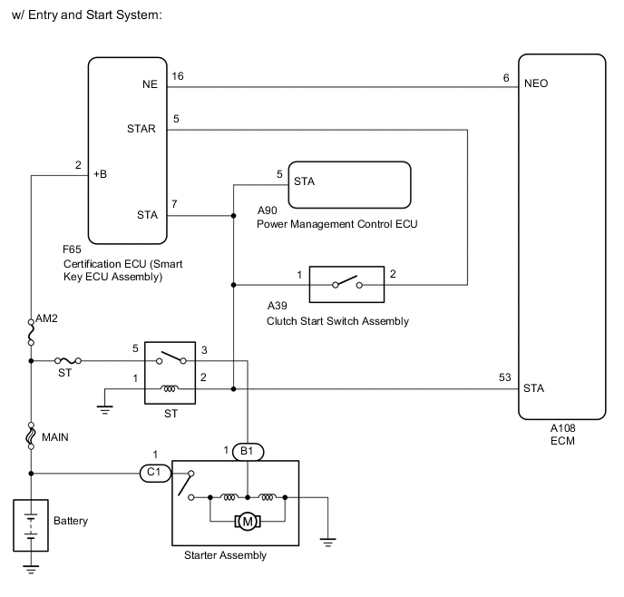
-
*1: w/ Entry and Start System
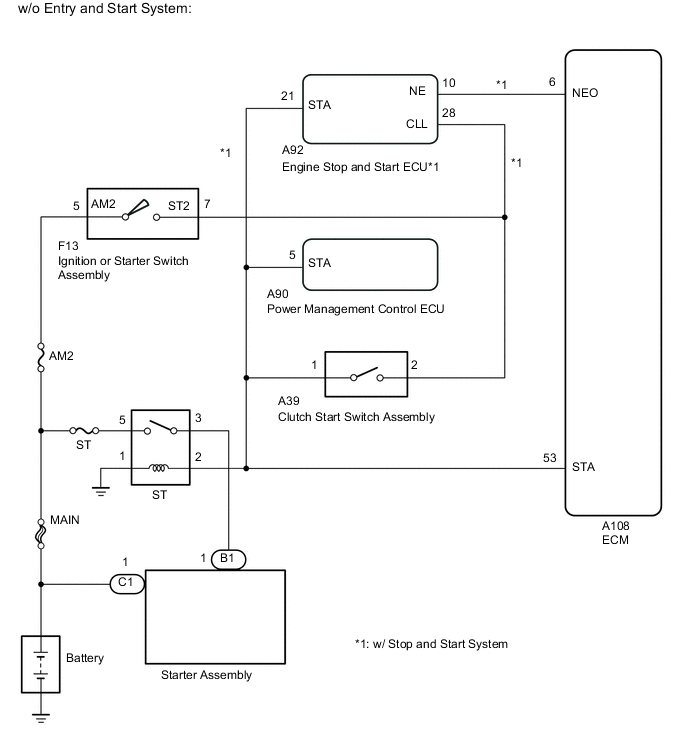
-
*2: w/o Entry and Start System
| DTC No. | Data List |
|---|---|
| P0617 | Starter Signal |
WIRING DIAGRAM
CAUTION / NOTICE / HINT
Note
-
When replacing the ECM, the ECM needs Registration and Initialization Click here.
-
Inspect the fuses for circuits related to this system before performing the following inspection procedure.
Tech Tips
-
The following troubleshooting process is based on the premise that the engine can crank normally.
If the engine does not crank, proceed to the Problem Symptoms Table Click here.
-
When the ECM must be replaced, before replacing the ECM, perform the "Learning Values Save" function using the GTS. Then after installing a new ECM, perform all of the initialization and registration procedures for the "Learning Values Write" function by following the instructions shown on the GTS display.
-
Read freeze frame data using the GTS. Freeze frame data records the engine condition when malfunctions are detected. When troubleshooting, freeze frame data can help determine if the vehicle was moving or stationary, if the engine was warmed up or not, and other data from the time the malfunction occurred.
PROCEDURE
-
READ VALUE USING GTS (STARTER SIGNAL)
-
Connect the GTS to the DLC3.
-
Turn the ignition switch to ON.
-
Turn the GTS on.
-
Enter the following menus: Powertrain / Engine and ECT / Data List / Starter Signal.
-
Check the value displayed on the GTS when the vehicle is driven at 20 km/h (12.4 mph) or more.
Note
When performing the confirmation driving pattern, obey all speed limits and traffic laws.
Result Condition Result Proceed to Driving at 20 km/h (12.4 mph) or more OFF A ON B
A 
CHECK FOR INTERMITTENT PROBLEMS Click here
B 
-
-
READ VALUE USING GTS (STARTER SIGNAL)
-
Disconnect the A28 clutch start switch assembly connector.
-
Connect the GTS to the DLC3.
-
Turn the ignition switch to ON.
-
Turn the GTS on.
-
Enter the following menus: Powertrain / Engine and ECT / Data List / Starter Signal.
-
Read the value displayed on the GTS when the ignition switch is ON.
Result Result Proceed to ON A OFF B
B 
INSPECT CLUTCH START SWITCH ASSEMBLY Click here
A
-
-
INSPECT ECM (STA TERMINAL VOLTAGE)
-
Disconnect the A28 clutch start switch assembly connector.
-
Disconnect the A108 ECM connector.
-
Turn the ignition switch to ON.
-
Measure the voltage according to the value(s) in the table below.
Standard Voltage Tester Connection Switch Condition Specified Condition Proceed to A108-53 (STA) - Body ground Ignition switch ON 11 to 14 V A*1 B*2 Below 1.5 V C
-
*1: w/ Entry and Start System
-
*2: w/o Entry and Start System
-
B
REPAIR OR REPLACE HARNESS OR CONNECTOR (ST RELAY - CLUTCH START SWITCH ASSEMBLY - ECM)
C
REPLACE ECM Click here
A
-
-
CHECK HARNESS AND CONNECTOR (ST RELAY - CLUTCH START SWITCH ASSEMBLY - ECM - CERTIFICATION ECU (SMART KEY ECU ASSEMBLY))
-
Remove the ST relay from the engine room relay block.
-
Disconnect the A39 clutch start switch assembly connector.
-
Disconnect the A108 ECM connector.
-
Disconnect the F65 certification ECU (smart key ECU assembly) connector.
-
Measure the resistance according to the value(s) in the table below.
Standard Resistance Tester Connection Condition Specified Condition 2 (ST relay holder), A39-1, A108-53 (STA) or F65-7 (STA) - Body ground Always 10 kΩ or higher
OK
REPLACE CERTIFICATION ECU (SMART KEY ECU ASSEMBLY)
NG
REPAIR OR REPLACE HARNESS OR CONNECTOR
-
-
INSPECT CLUTCH START SWITCH ASSEMBLY
-
Inspect the clutch start switch assembly Click here.
Result Result Proceed to NG A OK (w/ Entry and Start System) B OK (w/o Entry and Start System) C
B
CHECK HARNESS AND CONNECTOR (CLUTCH START SWITCH ASSEMBLY - ECM - CERTIFICATION ECU (SMART KEY ECU ASSEMBLY)) Click here
C
INSPECT IGNITION OR STARTER SWITCH ASSEMBLY Click here
A
-
-
REPLACE CLUTCH START SWITCH ASSEMBLY
-
Replace the clutch start switch assembly Click here.
Result Result Proceed to w/ Entry and Start System A w/o Entry and Start System B
B
INSPECT IGNITION OR STARTER SWITCH ASSEMBLY Click here
A
-
-
CHECK HARNESS AND CONNECTOR (CLUTCH START SWITCH ASSEMBLY - ECM - CERTIFICATION ECU (SMART KEY ECU ASSEMBLY))
-
Disconnect the A39 clutch start switch assembly connector.
-
Disconnect the F65 certification ECU (smart key ECU assembly) connector.
-
Measure the resistance according to the value(s) in the table below.
Standard Resistance Tester Connection Condition Specified Condition A39-2 or F65-5 (STAR) - Body ground Always 10 kΩ or higher
OK
REPLACE CERTIFICATION ECU (SMART KEY ECU ASSEMBLY)
NG
REPAIR OR REPLACE HARNESS OR CONNECTOR
-
-
INSPECT IGNITION OR STARTER SWITCH ASSEMBLY
-
Inspect the ignition or starter switch assembly Click here.
NG
REPLACE IGNITION OR STARTER SWITCH ASSEMBLY Click here
OK
-
-
CHECK HARNESS AND CONNECTOR (CLUTCH START SWITCH ASSEMBLY - ECM - IGNITION OR STARTER SWITCH ASSEMBLY)
-
Disconnect the A39 clutch start switch assembly connector.
-
Disconnect the F13 ignition or starter switch assembly connector.
-
Measure the resistance according to the value(s) in the table below.
Standard Resistance Tester Connection Condition Specified Condition A39-2 or F13-7 (ST2) - Body ground Always 10 kΩ or higher
OK
REPLACE ECM Click here
NG
REPAIR OR REPLACE HARNESS OR CONNECTOR
-