ECD SYSTEM(w/ DPF) ECM Power Source Circuit
DESCRIPTION
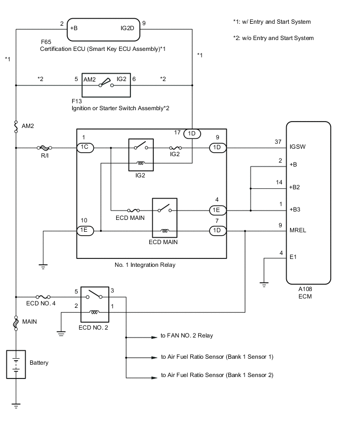
When the ignition switch is turned to ON, the battery voltage is applied to the IGSW terminal of the ECM. The output signal from the MREL terminal of the ECM causes a current to flow to the ECD MAIN relay coil and ECD NO. 2 relay coil, closing the ECD MAIN relay and ECD NO. 2 relay contacts and supplying power to terminal +B, +B2 and +B3 of the ECM.
WIRING DIAGRAM
CAUTION / NOTICE / HINT
Note
-
When replacing the ECM, the ECM needs Registration and Initialization Click here.
-
Inspection the fuses for circuits related to this system before performing the following inspection procedure.
Tech Tips
When the ECM must be replaced, before replacing the ECM, perform the "Learning Values Save" function using the GTS. Then after installing the new ECM, perform all of the initialization/registrations for the "Learning Values Write" function by following the instructions shown on the GTS display.
PROCEDURE
-
CHECK HARNESS AND CONNECTOR (POWER SOURCE)
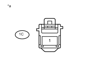
Text in Illustration *a Front view of wire harness connector
(to No. 1 Integration Relay)
-
Remove the No. 1 integration relay from the engine room relay block.
-
Measure the voltage according to the value(s) in the table below.
Standard Voltage Tester Connection Condition Specified Condition 1C-1 - Body ground Always 11 to 14 V
NG 
REPAIR OR REPLACE HARNESS OR CONNECTOR (NO. 1 INTEGRATION RELAY - BATTERY)
OK 
-
-
INSPECT NO. 1 INTEGRATION RELAY (ECD MAIN RELAY AND IG2 RELAY)
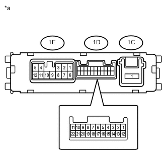
Text in Illustration *a Component without harness connected
(No. 1 Integration Relay)
-
Remove the No. 1 integration relay from the engine room relay block.
-
Measure the resistance according to the value(s) in the table below.
Standard Resistance Tester Connection Condition Specified Condition 1C-1 - 1D-9 Battery voltage not applied 10 kΩ or higher Battery voltage applied to terminals 1D-17 and 1E-10 Below 1 Ω 1C-1 - 1E-4 Battery voltage not applied 10 kΩ or higher Battery voltage applied to terminals 1D-7 and 1E-10 Below 1 Ω
NG
REPLACE NO. 1 INTEGRATION RELAY Click here
OK
-
-
CHECK TERMINAL VOLTAGE (POWER SOURCE OF ECD NO. 2 RELAY)
-
Remove the air pump heater relay from the engine room relay block.
-
Measure the voltage according to the value(s) in the table below.
Standard Voltage Tester Connection Switch Condition Specified Condition 5 (ECD NO. 2 relay holder) - Body ground Always 11 to 14 V
NG
REPAIR OR REPLACE HARNESS OR CONNECTOR (ECD NO. 2 RELAY - BATTERY)
OK
-
-
INSPECT ECD NO. 2 RELAY
-
Remove the air pump heater relay from the engine room relay block.
-
Measure the resistance according to the value(s) in the table below.
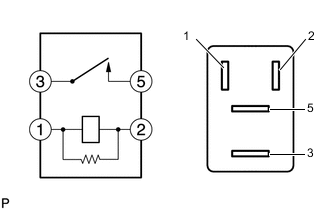
Standard Resistance Tester Connection Condition Specified Condition 3 - 5 Battery voltage not applied 10 kΩ or higher Battery voltage applied to terminals 1 and 2 Below 1 Ω
NG
REPLACE ECD NO. 2 RELAY
OK
-
-
CHECK HARNESS AND CONNECTOR (NO. 1 INTEGRATION RELAY - ECD NO. 2 RELAY - ECM)
-
Remove the No. 1 integration relay from the engine room relay block.
-
Remove the ECD NO. 2 relay from the No. 2 engine room relay block.
-
Disconnect the A108 ECM connector.
-
Measure the resistance according to the value(s) in the table below.
Standard Resistance Tester Connection Condition Specified Condition A108-9 (MREL) - 1D-7 Always Below 1 Ω A108-2 (+B) - 1E-4 Always Below 1 Ω A108-14 (+B2) - 1E-4 Always Below 1 Ω A108-1 (+B3) - 1E-4 Always Below 1 Ω A108-9 (MREL) - 1 (ECD NO. 2 relay holder) Always Below 1 Ω A108-9 (MREL) or 1D-7 - Body ground Always 10 kΩ or higher A108-2 (+B) or 1E-4 - Body ground Always 10 kΩ or higher A108-14 (+B2) or 1E-4 - Body ground Always 10 kΩ or higher A108-1 (+B3) or 1E-4 - Body ground Always 10 kΩ or higher A108-9 (MREL) or 1 (ECD NO. 2 relay holder) - Body ground Always 10 kΩ or higher
NG
REPAIR OR REPLACE HARNESS OR CONNECTOR
OK
-
-
CHECK HARNESS AND CONNECTOR (ECM - BODY GROUND)
-
Disconnect the A108 ECM connector.
-
Measure the resistance according to the value(s) in the table below.
Standard Resistance Tester Connection Condition Specified Condition A108-4 (E1) - Body ground Always Below 1 Ω
NG
REPAIR OR REPLACE HARNESS OR CONNECTOR
OK
-
-
CHECK HARNESS AND CONNECTOR (IGSW TERMINAL VOLTAGE)
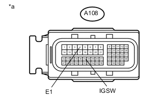
Text in Illustration *a Front view of wire harness connector
(to ECM)
-
Disconnect the ECM connector.
-
Turn the ignition switch to ON.
-
Measure the voltage according to the value(s) in the table below.
Standard Voltage Tester Connection Switch Condition Specified Condition A108-37 (IGSW) - A108-4 (E1) Ignition switch ON 11 to 14 V Result Result Proceed to Outside standard range A Within standard range B
B
REPLACE ECM Click here
A
-
-
CHECK HARNESS AND CONNECTOR (ECM - NO. 1 INTEGRATION RELAY)
-
Remove the No. 1 integration relay from the engine room relay block.
-
Disconnect the A108 ECM connector.
-
Measure the resistance according to the value(s) in the table below.
Standard Resistance Tester Connection Condition Specified Condition A108-37 (IGSW) - 1D-9 Always Below 1 Ω A108-37 (IGSW) or 1D-9 - Body ground Always 10 kΩ or higher Result Result Proceed to Outside standard range A Within standard range (w/ Entry and Start System) B Within standard range (w/o Entry and Start System) C
A
REPAIR OR REPLACE HARNESS OR CONNECTOR
C 
CHECK HARNESS AND CONNECTOR (IGNITION OR STARTER SWITCH ASSEMBLY - NO. 1 INTEGRATION RELAY - BODY GROUND) Click here
B
-
-
CHECK HARNESS AND CONNECTOR (NO. 1 INTEGRATION RELAY - CERTIFICATION ECU (SMART KEY ECU ASSEMBLY))
-
Remove the No. 1 integration relay from the engine room relay block.
-
Disconnect the F65 certification ECU (smart key ECU assembly) connector.
-
Measure the resistance according to the value(s) in the table below.
Standard Resistance Tester Connection Condition Specified Condition 1D-17- F65-9 (IG2D) Always Below 1 Ω 1E-10 - Body ground Always Below 1 Ω F65-9 (IG2D) or 1D-17 - Body ground Always 10 kΩ or higher
OK
GO TO ENTRY AND START SYSTEM Click here
NG
REPAIR OR REPLACE HARNESS OR CONNECTOR
-
-
CHECK HARNESS AND CONNECTOR (IGNITION OR STARTER SWITCH ASSEMBLY - NO. 1 INTEGRATION RELAY - BODY GROUND)
-
Remove the No. 1 integration relay from the engine room relay block.
-
Disconnect the F13 ignition or starter switch assembly connector.
-
Measure the resistance according to the value(s) in the table below.
Standard Resistance Tester Connection Condition Specified Condition 1D-17 - F13-6 (IG2) Always Below 1 Ω 1E-10 - Body ground Always Below 1 Ω F13-6 (IG2) or 1D-17 - Body ground Always 10 kΩ or higher
NG
REPAIR OR REPLACE HARNESS OR CONNECTOR
OK
-
-
INSPECT IGNITION OR STARTER SWITCH ASSEMBLY
-
Inspect the ignition or starter switch assembly Click here.
OK
REPAIR OR REPLACE HARNESS OR CONNECTOR (IGNITION OR STARTER SWITCH ASSEMBLY - BATTERY)
NG
REPLACE IGNITION OR STARTER SWITCH ASSEMBLY Click here
-