ECD SYSTEM(w/ DPF), Diagnostic DTC:P2454, P2455
| DTC Code | DTC Name |
|---|---|
| P2454 | Diesel Particulate Filter Pressure Sensor "A" Circuit Low |
| P2455 | Diesel Particulate Filter Pressure Sensor "A" Circuit High |
DESCRIPTION
The ECM compares the exhaust gas pressure before and after DPF* catalytic converter using the semiconductor-type differential pressure sensor.
If the differential pressure exceeds a predetermined level, the ECM judges that the catalytic converter has clogged with particulate matter (PM). At that time, the ECM begins to perform DPF catalyst regeneration.
*: Diesel Particulate Filter
| DTC Detection Drive Pattern | DTC Detection Condition | Trouble Area |
|---|---|---|
| Ignition switch ON for 2 seconds | Differential pressure sensor output voltage is 0.35 V or less for 2 seconds. (2 trip detection logic) |
|
| DTC Detection Drive Pattern | DTC Detection Condition | Trouble Area |
|---|---|---|
| Ignition switch ON for 2 seconds | Differential pressure sensor output voltage is 4.9 V or more 2 seconds. (2 trip detection logic) |
|
| DTC No. | Data List |
|---|---|
| P2454 | DPF Differential Pressure |
| P2455 |
Tech Tips
If the Differential Pressure outputs a negative value when the engine is maintained at an engine speed of 3000 rpm with no load, the hose and pipe connections may be incorrect.
WIRING DIAGRAM
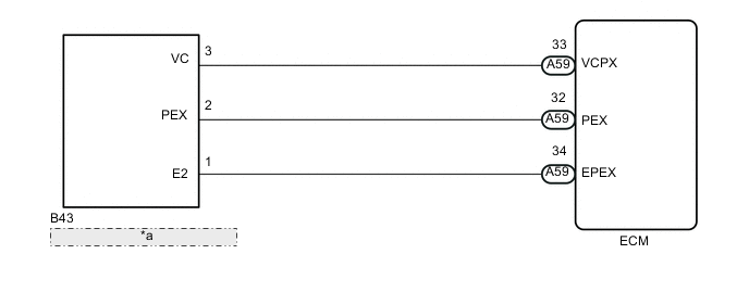
| *a | Differential Pressure Sensor |
CAUTION / NOTICE / HINT
Note
When replacing the ECM, the ECM needs Registration and Initialization Click here.
Tech Tips
-
When the ECM must be replaced, before replacing the ECM, perform the "Learning Values Save" function using the intelligent tester. Then after installing the new ECM, perform all of the initialization/registrations for the "Learning Values Write" function by following the instructions shown on the tester display.
-
Read freeze frame data using the intelligent tester. Freeze frame data records the engine condition when malfunctions are detected. When troubleshooting, freeze frame data can help determine if the vehicle was moving or stationary, if the engine was warmed up or not, and other data from the time the malfunction occurred.
PROCEDURE
-
READ VALUE USING INTELLIGENT TESTER (DPF DIFFERENTIAL PRESSURE)
-
Connect the intelligent tester to the DLC3.
-
Start the engine and turn the tester on.
-
Depress and release the accelerator pedal repeatedly several times.
-
Enter the following menus: Powertrain / Engine and ECT / Data List / DPF Differential Pressure.
-
Read the value when depress and release the accelerator pedal.
Result Result Condition Proceed to -5 kPa Always A 99 kPa or more Always B Between -4 to 98 kPa Engine running
depress and release accelerator pedal
C
B 
CHECK BLOCKAGE OF EXHAUST PIPE AIR HOSE AND TRANSMITTING PIPE Click here
C 
CHECK FOR INTERMITTENT PROBLEMS Click here
A 
-
-
CHECK CONNECTION OF EXHAUST PIPE AIR HOSE (DIFFERENTIAL PRESSURE SENSOR - EXHAUST PIPE AIR HOSE)
-
Check if the exhaust pipe air hose routing between the differential pressure sensor and the vacuum transmitting pipe is correct.
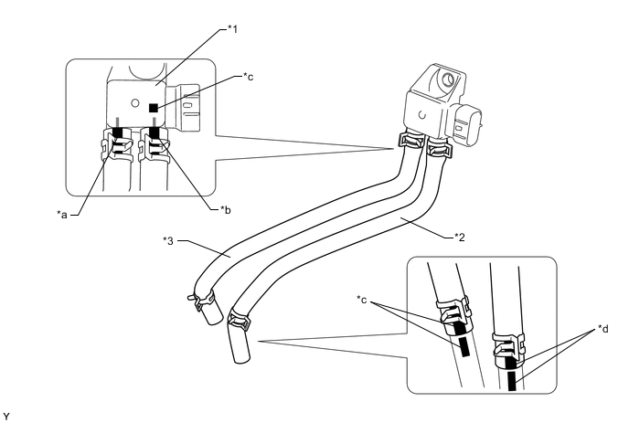
Text in Illustration *1 Differential Pressure Sensor *2 No. 1 Vacuum Transmitting Hose (for upstream) *3 No. 1 Vacuum Transmitting Hose (for downstream) - - *a Marked: Yellow *b Marked: Pink *c Marked: Red *d Marked: Orange -
Check that there is no exhaust gas leak between the differential pressure sensor and the vacuum transmitting pipe.
OK Exhaust pipe air hose routing is correct and there is no exhaust gas leak.
NG
REPAIR OR REPLACE MALFUNCTIONING PARTS Click here
OK
-
-
CHECK BLOCKAGE OF EXHAUST PIPE AIR HOSE AND TRANSMITTING PIPE
CAUTION:
Be careful of being burned by exhaust gases during the following inspection.
-
Disconnect the exhaust pipe air hose (both upstream and downstream) on the differential pressure sensor.
-
Start the engine.
-
Check if there are exhaust gas pulsations from both exhaust pipe air hoses during idling.
NG
REPAIR OR REPLACE MALFUNCTIONING PARTS Click here
OK
-
-
CHECK HARNESS AND CONNECTOR (DIFFERENTIAL PRESSURE SENSOR - ECM)
-
Disconnect the differential pressure sensor connector.
-
Disconnect the ECM connector.
-
Measure the resistance according to the value(s) in the table below.
Standard Resistance Tester Connection Condition Specified Condition B43-2 (PEX) - A59-32 (PEX) Always Below 1 Ω B43-3 (VC) - A59-33 (VCPX) Always Below 1 Ω B43-1 (E2) - A59-34 (EPEX) Always Below 1 Ω B43-2 (PEX) or A59-32 (PEX) - Body ground Always 10 kΩ or higher B43-3 (VC) or A59-33 (VCPX) - Body ground Always 10 kΩ or higher B43-1 (E2) or A59-34 (EPEX) - Body ground Always 10 kΩ or higher
NG
REPAIR OR REPLACE HARNESS OR CONNECTOR Click here
OK
-
-
REPLACE DIFFERENTIAL PRESSURE SENSOR
-
Replace the differential pressure sensor Click here.
-
Start the engine and wait until the engine coolant temperature reaches 75°C (167°F) or more (A).
-
Turn the ignition switch off and wait for 30 seconds or more (B).
-
Repeat the above procedures (A) and (B) 3 times.
Tech Tips
Procedures (A) and (B) must be repeated 3 times to complete the differential pressure sensor learning process.
NEXT
-
-
CHECK WHETHER DTC OUTPUT RECURS (DTC P2454 OR P2455)
-
Connect the intelligent tester to the DLC3.
-
Turn the ignition switch to ON and turn the tester on.
-
Clear the DTCs Click here.
-
Turn the ignition switch off and wait for 30 seconds or more.
-
Turn the ignition switch to ON and wait for 10 seconds or more.
-
Enter the following menus: Powertrain / Engine and ECT / DTC / Pending.
-
Read the pending DTCs.
Result Result Proceed to DTC P2454 or P2455 A No DTC output B
B
END
A
-
-
REPLACE ECM
-
Replace the ECM Click here.
NEXT
CONFIRM WHETHER MALFUNCTION HAS BEEN SUCCESSFULLY REPAIRED Click here
-
-
REPAIR OR REPLACE HARNESS OR CONNECTOR
NEXT
CONFIRM WHETHER MALFUNCTION HAS BEEN SUCCESSFULLY REPAIRED Click here
-
REPAIR OR REPLACE MALFUNCTIONING PARTS
NEXT
-
CONFIRM WHETHER MALFUNCTION HAS BEEN SUCCESSFULLY REPAIRED
-
Connect the intelligent tester to the DLC3.
-
Turn the ignition switch to ON and turn the tester on.
-
Clear the DTCs Click here.
-
Turn the ignition switch off and wait for 30 seconds or more.
-
Turn the ignition switch to ON and wait for 10 seconds or more.
-
Enter the following menus: Powertrain / Engine and ECT / DTC / Pending.
-
Confirm that the pending DTC is not output again.
NEXT
END
-