BRAKE PEDAL(for TMMF Made) ADJUSTMENT
PROCEDURE
-
INSPECT AND ADJUST BRAKE PEDAL
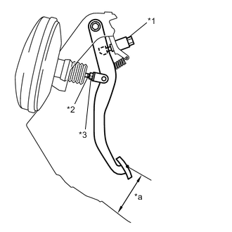
Text in Illustration *1 Stop Light Switch Assembly *2 Push Rod *3 Push Rod Lock Nut *a Pedal Height
-
Inspect the brake pedal height.
Pedal height from floor for LHD for RHD 130.8 to 140.8 mm (5.15 to 5.54 in.) 130.6 to 140.6 mm (5.15 to 5.54 in.) If the pedal height is incorrect, adjust it.
-
Adjust the brake pedal height.
-
Disconnect the connector from the stop light switch.
-
Turn the stop light switch counterclockwise and remove the stop light switch.
-
Loosen the push rod lock nut.
-
Adjust the pedal height by turning the pedal push rod.
Pedal height from floor for LHD for RHD 130.8 to 140.8 mm (5.15 to 5.54 in.) 130.6 to 140.6 mm (5.15 to 5.54 in.) -
Tighten the push rod lock nut.
- Torque:
- 15 N*m { 153 kgf*cm, 11 ft.*lbf }
-
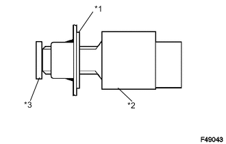
Text in Illustration *1 Adjuster *2 Stop Light Switch Assembly *3 Brake Pedal Insert the stop light switch into the adjuster until it just touches the brake pedal.
Note
Do not depress the brake pedal.
-
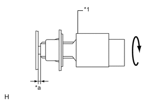
Text in Illustration *1 Stop Light Switch Assembly *a Stop Light Switch Clearance Make a quarter turn clockwise to install the stop light switch.
Note
Do not depress the brake pedal.
Tech Tips
The turning torque for installing the stop light switch:
- Torque:
- 1.5 N*m { 15 kgf*cm, 13 in.*lbf }
- or less
-
Check the stop light switch clearance.
Stop light switch clearance 0.5 to 2.6 mm (0.020 to 0.102 in.) -
Connect the connector to the stop light switch.
-
-
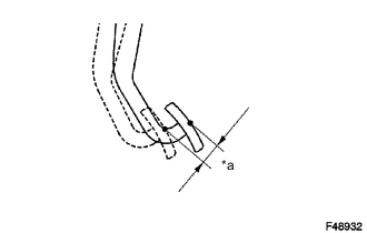
Text in Illustration *a Pedal Free Play Inspect the brake pedal free play.
-
Stop the engine and depress the brake pedal several times until there is no vacuum left in the booster.
-
Push in the pedal until a slight resistance is felt. Measure the distance as shown.
Pedal free play 1.0 to 6.0 mm (0.0394 to 0.236 in.) If incorrect, troubleshoot the brake system.
-
-
Inspect the brake pedal reserve distance.
-
Release the parking brake lever. With the engine running, depress the pedal and measure the pedal reserve distance as shown.
Pedal reserve distance from floor at 300 N (31 kgf, 67.4 lbf) Engine Type Rear Brake Type for LHD for RHD except 1ND-TV Drum More than 83 mm (3.27 in.) More than 76 mm (2.99 in.) Disc More than 79 mm (3.11 in.) More than 74 mm (2.91 in.) for 1ND-TV Drum More than 81 mm (3.19 in.) More than 75 mm (2.95 in.) Disc More than 78 mm (3.07 in.) More than 73 mm (2.87 in.) Tech Tips
Measure the pedal height between the floor base surface and the pedal as shown in the illustration.
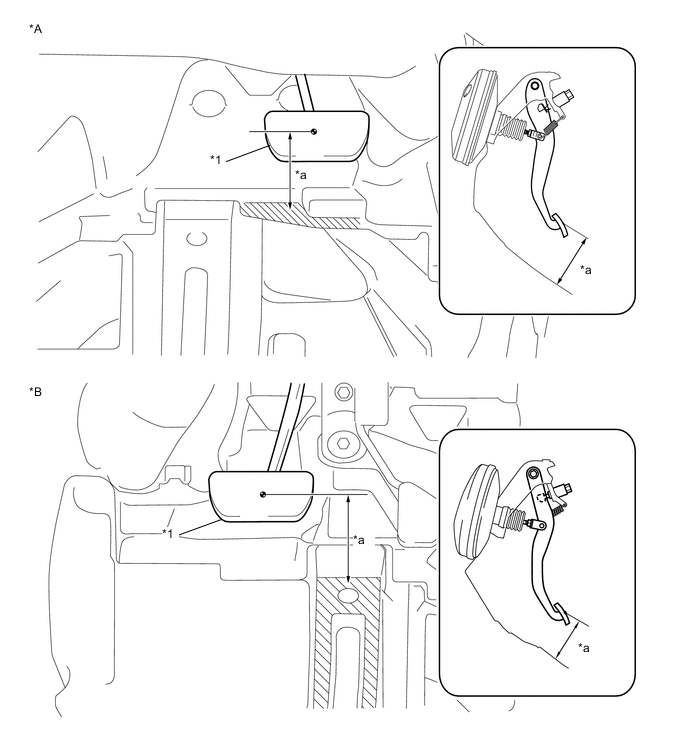
Text in Illustration *A for LHD *B for RHD *1 Brake Pedal - - *a Reserve Distance - - 
Measuring Plane - - Tech Tips
Sound and resistance from the brake booster when the brake pedal is depressed without a vacuum does not indicate a problem.
If incorrect, troubleshoot the brake system.
-
-