VEHICLE STABILITY CONTROL SYSTEM(for TMMF Made) TC and CG Terminal Circuit
DESCRIPTION
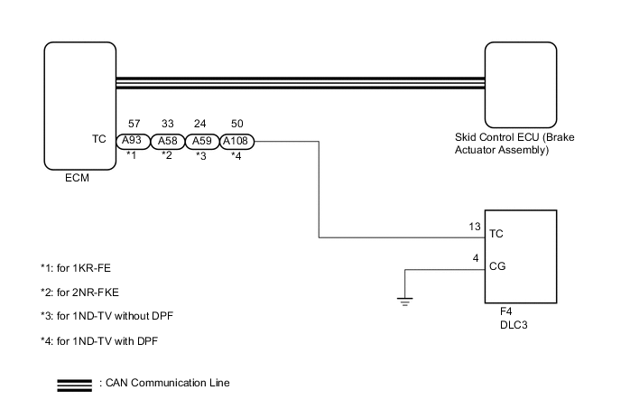
Connecting terminals 13 (TC) and 4 (CG) of the DLC3 causes the ECU to output the DTCs by blinking the ABS warning light and slip indicator light.
WIRING DIAGRAM
-
except GRMN
Tech Tips
When the warning lights continue to blink, a ground short in the wiring of terminal 13 (TC) of the DLC3 or an internal ground short in one or more ECUs is suspected.
-
for GRMN
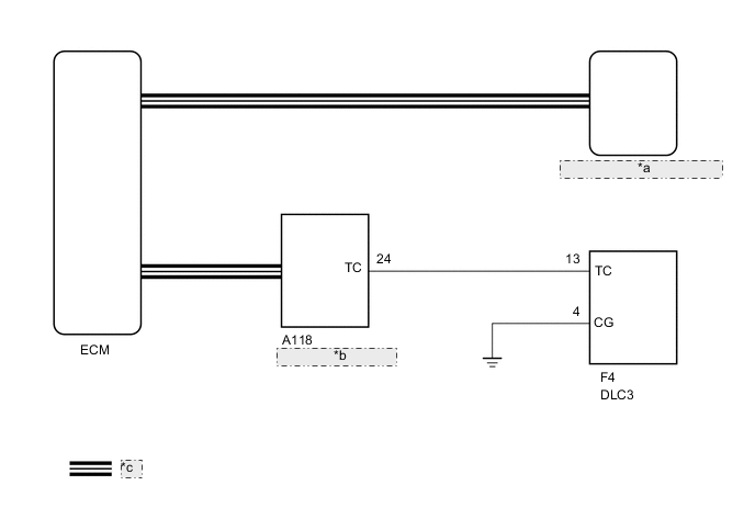
*a Skid Control ECU (Brake Actuator Assembly) *b Network Gateway ECU *c CAN Communication Line Tech Tips
When the warning lights continue to blink, a ground short in the wiring of terminal 13 (TC) of the DLC3 or an internal ground short in one or more ECUs is suspected.
CAUTION / NOTICE / HINT
Note
When replacing the brake actuator assembly, perform calibration Click here.
PROCEDURE
-
CHECK CAN COMMUNICATION SYSTEM
-
Check if CAN communication system DTCs are output.
-
w/o Toyota Safety Sense Click here
-
w/ Toyota Safety Sense Click here
Result Result Proceed to DTC not output A DTC output (w/o Toyota Safety Sense) B DTC output (w/ Toyota Safety Sense) C -
B 
GO TO CAN COMMUNICATION SYSTEM Click here
C
GO TO CAN COMMUNICATION SYSTEM Click here
A 
-
-
INSPECT DLC3
-
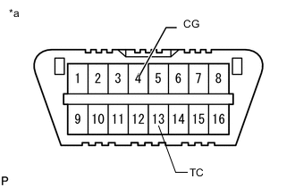
Text in Illustration *a Front view of DLC3 Measure the voltage according to the value(s) in the table below.
Standard Voltage Tester Connection Switch Condition Specified Condition F4-13 (TC) - Body ground Ignition switch ON 11 to 14 V Result Result Proceed to OK A NG (except GRMN) B NG (for GRMN) C
B 
CHECK HARNESS AND CONNECTOR (DLC3 - ECM) Click here
C
CHECK HARNESS AND CONNECTOR (DLC3 - NETWORK GATEWAY ECU) Click here
A
-
-
INSPECT ECM (DLC3 INPUT)
- SST
- 09843-18040
-
Turn the ignition switch off.
-
Text in Illustration *a Front view of DLC3 Using SST, connect terminals 13 (TC) and 4 (CG) of the DLC3.
-
Turn the ignition switch to ON.
-
Check that the MIL is blinking.
Result Result Proceed to MIL is not blinking (except GRMN) A MIL is not blinking (for GRMN) B MIL is blinking (for LHD) C MIL is blinking (for RHD) D
B
CHECK HARNESS AND CONNECTOR (DLC3 - NETWORK GATEWAY ECU) Click here
C
REPLACE BRAKE ACTUATOR ASSEMBLY Click here
D
REPLACE BRAKE ACTUATOR ASSEMBLY Click here
A
-
CHECK HARNESS AND CONNECTOR (DLC3 - ECM)
-
Disconnect the A93*1, A58*2, A59*3 or A108*4 ECM connector.
-
*1: for 1KR-FE
-
*2: for 2NR-FKE
-
*3: for 1ND-TV without DPF
-
*4: for 1ND-TV with DPF
-
-
Measure the resistance according to the value(s) in the table below.
Standard Resistance (for 1KR-FE) Tester Connection Condition Specified Condition F4-13 (TC) - A93-57 (TC) Always Below 1 Ω F4-13 (TC) or A93-57 (TC) - Body ground Always 10 kΩ or higher Standard Resistance (for 2NR-FKE) Tester Connection Condition Specified Condition F4-13 (TC) - A58-33 (TC) Always Below 1 Ω F4-13 (TC) or A58-33 (TC) - Body ground Always 10 kΩ or higher Standard Resistance (for 1ND-TV without DPF) Tester Connection Condition Specified Condition F4-13 (TC) - A59-24 (TC) Always Below 1 Ω F4-13 (TC) or A59-24 (TC) - Body ground Always 10 kΩ or higher Standard Resistance (for 1ND-TV with DPF) Tester Connection Condition Specified Condition F4-13 (TC) - A108-50 (TC) Always Below 1 Ω F4-13 (TC) or A108-50 (TC) - Body ground Always 10 kΩ or higher
OK
CHECK HARNESS AND CONNECTOR (DLC3 - BODY GROUND) Click here
NG
REPAIR OR REPLACE HARNESS OR CONNECTOR
-
-
CHECK HARNESS AND CONNECTOR (DLC3 - NETWORK GATEWAY ECU)
-
Disconnect the A118 network gateway ECU connector.
-
Measure the resistance according to the value(s) in the table below.
Standard Resistance Tester Connection Condition Specified Condition F4-13 (TC) - A118-24 (TC) Always Below 1 Ω F4-13 (TC) or A118-24 (TC) - Body ground Always 10 kΩ or higher
OK
CHECK HARNESS AND CONNECTOR (DLC3 - BODY GROUND) Click here
NG
REPAIR OR REPLACE HARNESS OR CONNECTOR
-
-
CHECK HARNESS AND CONNECTOR (DLC3 - BODY GROUND)
-
Measure the resistance according to the value(s) in the table below.
Standard Resistance Tester Connection Condition Specified Condition F4-4 (CG) - Body ground Always Below 1 Ω Result Result Proceed to NG A OK (for 1KR-FE) B OK (for 2NR-FKE) C OK (for 1ND-TV without DPF) D OK (for 1ND-TV with DPF) E
A
REPAIR OR REPLACE HARNESS OR CONNECTOR
B
REPLACE ECM Click here
C
REPLACE ECM Click here
D
REPLACE ECM Click here
E
REPLACE ECM Click here
-
-
CHECK HARNESS AND CONNECTOR (DLC3 - BODY GROUND)
-
Measure the resistance according to the value(s) in the table below.
Standard Resistance Tester Connection Condition Specified Condition F4-4 (CG) - Body ground Always Below 1 Ω
OK
REPLACE NETWORK GATEWAY ECU Click here
NG
REPAIR OR REPLACE HARNESS OR CONNECTOR
-