VEHICLE STABILITY CONTROL SYSTEM(for TMMF Made), Diagnostic DTC:C1231

| DTC Code | DTC Name |
|---|---|
| C1231 | Steering Angle Sensor Circuit |
DESCRIPTION
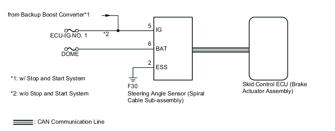
The steering angle sensor signal is sent to the skid control ECU via the CAN communication system. When there is a malfunction in the CAN communication system, it is detected by the diagnostic function.
| DTC No. | DTC Detection Condition | Trouble Area |
|---|---|---|
| C1231 | When any of following conditions detected:
|
|
Tech Tips
*1: DTC C1231 (DTC detection condition No. 2) is erased automatically when the ignition switch is turned from off to ON after the voltage supply to the steering angle sensor returns to normal.
WIRING DIAGRAM
CAUTION / NOTICE / HINT
Tech Tips
When U0126 is output together with C1231, inspect and repair the trouble areas indicated by U0126 first.
Note
-
When replacing the brake actuator assembly, perform zero point calibration Click here.
-
Inspect the fuses for circuits related to this system before performing the following inspection procedure.
PROCEDURE
-
READ VALUE USING INTELLIGENT TESTER (STEERING ANGLE SENSOR)
-
Connect the intelligent tester to the DLC3.
-
Turn the ignition switch to ON.
-
Turn the tester on.
-
Check that the steering wheel is centered.
-
Enter the following menu: Chassis / ABS/VSC/TRC / Data List.
-
In accordance with the display on the tester, read the Data List.
ABS/VSC/TRC Tester Display Measurement Item/Range Normal Condition Diagnostic Note Steering Angle Sensor Steering angle sensor reading:
min.: -3276.8 deg, max.: 3276.7 deg
Left turn: Increase
Right turn: Decrease
- Steering Angle Value Steering angle value:
min.: -3276.8 deg, max.: 3276.7 deg
Left turn: Increase
Right turn: Decrease
- -
Check that the steering wheel turning angle of the steering angle sensor changes when turning the steering wheel. The changes in the value should precisely match the movements of the steering wheel.
OK Turning the steering wheel to the left: Value increases in proportion to the angle the steering wheel is turned Turning the steering wheel to the right: Value decreases in proportion to the angle the steering wheel is turned
NG 
CHECK CAN COMMUNICATION SYSTEM Click here
OK 
-
-
RECONFIRM DTC
-
Clear the DTC Click here.
-
Start the engine.
-
Drive the vehicle and turn the steering wheel to the right and left at a speed of 45 km/h (28 mph) or more for several seconds.
-
Check if the same DTC is recorded Click here.
Result Result Proceed to DTC C1231 is not output A DTC C1231 is output (for LHD) B DTC C1231 is output (for RHD) C
A 
CHECK FOR INTERMITTENT PROBLEMS Click here
B
REPLACE BRAKE ACTUATOR ASSEMBLY Click here
C
REPLACE BRAKE ACTUATOR ASSEMBLY Click here
-
-
CHECK CAN COMMUNICATION SYSTEM
-
Check if CAN communication system DTCs are output Click here.
Result Result Proceed to DTC not output A DTC output B
B
GO TO CAN COMMUNICATION SYSTEM Click here
A
-
-
CHECK STEERING ANGLE SENSOR (SPIRAL CABLE SUB-ASSEMBLY)
-
Check that the steering angle sensor (spiral cable sub-assembly) has been installed correctly Click here.
OK The sensor is installed correctly.
NG
INSTALL STEERING ANGLE SENSOR (SPIRAL CABLE SUB-ASSEMBLY) CORRECTLY
OK
-
-
CHECK HARNESS AND CONNECTOR (SKID CONTROL ECU - STEERING ANGLE SENSOR)
-
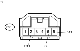
Text in Illustration *a Front view of wire harness connector
(to Steering Angle Sensor (Spiral Cable Sub-assembly))
Disconnect the steering angle sensor connector.
-
Measure the voltage according to the value(s) in the table below.
Standard Voltage Tester Connection Switch Condition Specified Conditions F30-5 (IG) - Body ground Ignition switch ON 11 to 14 V F30-6 (BAT) - Body ground Always 11 to 14 V -
Measure the resistance according to the value(s) in the table below.
Standard Resistance Tester Connection Switch Condition Specified Conditions D62-2 (ESS) - Body ground Ignition switch off Below 1 Ω
NG
REPAIR OR REPLACE HARNESS OR CONNECTOR
OK
-
-
REPLACE STEERING ANGLE SENSOR (SPIRAL CABLE SUB-ASSEMBLY)
-
Replace the steering angle sensor (spiral cable sub-assembly) Click here.
NEXT
-
-
RECONFIRM DTC
-
Clear the DTC Click here.
-
Start the engine.
-
Drive the vehicle and turn the steering wheel to the right and left at a speed of 45 km/h (28 mph) or more for several seconds.
-
Check if the same DTC is recorded Click here.
Result Result Proceed to DTC C1231 is not output A DTC C1231 is output (for LHD) B DTC C1231 is output (for RHD) C
A
END
B
REPLACE BRAKE ACTUATOR ASSEMBLY Click here
C
REPLACE BRAKE ACTUATOR ASSEMBLY Click here
-