VEHICLE STABILITY CONTROL SYSTEM(for TMMF Made), Diagnostic DTC:C1202

| DTC Code | DTC Name |
|---|---|
| C1202 | Master Reservoir Level Malfunction |
DESCRIPTION
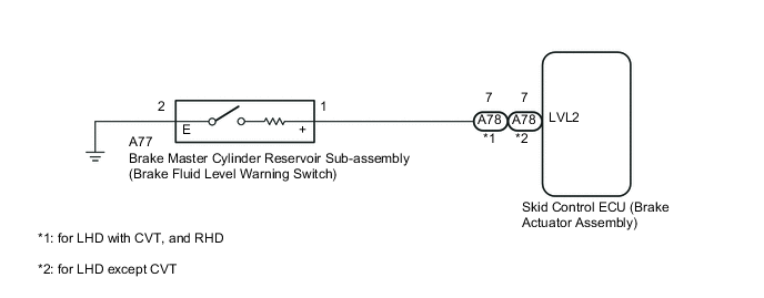
The brake fluid level warning switch sends the appropriate signal to the skid control ECU when the brake fluid level drops.
| DTC No. | DTC Detection Condition | Trouble Area |
|---|---|---|
| C1202 | Low fluid level condition in the brake master cylinder reservoir tank continues for 60 seconds. |
|
WIRING DIAGRAM
CAUTION / NOTICE / HINT
Note
When replacing the brake actuator assembly, perform zero point calibration Click here.
PROCEDURE
-
CHECK BRAKE FLUID LEVEL
-
Turn the ignition switch off.
-
Check the amount of fluid in the brake reservoir.
OK Brake fluid level is correct.
NG 
ADD BRAKE FLUID
OK 
-
-
INSPECT BRAKE MASTER CYLINDER RESERVOIR SUB-ASSEMBLY (BRAKE FLUID LEVEL WARNING SWITCH)
-
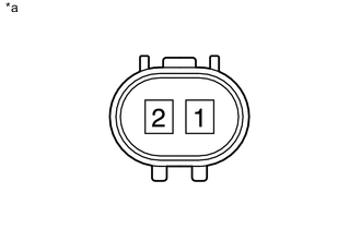
Text in Illustration *a Component without harness connected
(Brake Fluid Level Warning Switch)
Remove the reservoir tank cap and strainer.
-
Disconnect the brake fluid level warning switch connector.
-
Measure the resistance according to the value(s) in the table below.
Tech Tips
A float is placed inside the reservoir. Its position can be changed by increasing or decreasing the brake fluid level.
Standard Resistance Tester Connection Switch Condition Specified Condition 1 - 2 Float up (Switch OFF) 10 kΩ or higher Float down (Switch ON) Below 1 Ω Tech Tips
If the result is as specified, adjust the brake fluid level to the MAX level after measuring the resistance.
Result Result Proceed to OK A NG (for LHD) B NG (for RHD) C
B
REPLACE BRAKE MASTER CYLINDER RESERVOIR SUB-ASSEMBLY Click here
C
REPLACE BRAKE MASTER CYLINDER RESERVOIR SUB-ASSEMBLY Click here
A
-
-
CHECK HARNESS AND CONNECTOR (SKID CONTROL ECU - BRAKE FLUID LEVEL WARNING SWITCH)
-
Disconnect the skid control ECU connector.
-
Measure the resistance according to the value(s) in the table below.
Standard Resistance (for LHD with CVT, and RHD) Tester Connection Condition Specified Condition A78-7 (LVL2) - A77-1 (+) Always Below 1 Ω A77-2 (E) - Body ground Always Below 1 Ω A78-7 (LVL2) - Body ground Always 10 kΩ or higher Standard Resistance (for LHD except CVT) Tester Connection Condition Specified Condition A79-7 (LVL2) - A77-1 (+) Always Below 1 Ω A77-2 (E) - Body ground Always Below 1 Ω A79-7 (LVL2) - Body ground Always 10 kΩ or higher
NG
REPAIR OR REPLACE HARNESS OR CONNECTOR
OK
-
-
RECONFIRM DTC
-
Clear the DTC Click here.
-
Check if the same DTC is recorded Click here.
Result Result Proceed to DTC C1202 is not output A DTC C1202 is output (for LHD) B DTC C1202 is output (for RHD) C
A
CHECK FOR INTERMITTENT PROBLEMS Click here
B
REPLACE BRAKE ACTUATOR ASSEMBLY Click here
C
REPLACE BRAKE ACTUATOR ASSEMBLY Click here
-