VEHICLE STABILITY CONTROL SYSTEM(for TMMF Made), Diagnostic DTC:C1249

| DTC Code | DTC Name |
|---|---|
| C1249 | Open in Stop Light Switch Circuit |
DESCRIPTION
The skid control ECU (brake actuator assembly) detects the brake operating conditions through a signal transmitted by the stop light switch. The skid control ECU (brake actuator assembly) incorporates an open circuit detection circuit.
| DTC No. | DTC Detection Condition | Trouble Area |
|---|---|---|
| C1249 | When either of following (1 or 2) detected:
|
|
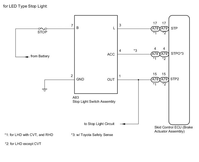
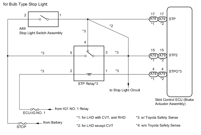
WIRING DIAGRAM
CAUTION / NOTICE / HINT
Note
-
When replacing the brake actuator assembly, perform zero point calibration Click here.
-
Inspect the fuses for circuits related to this system before performing the following inspection procedure.
PROCEDURE
-
READ VALUE USING INTELLIGENT TESTER (STOP LIGHT SW)
-
Connect the intelligent tester to the DLC3.
-
Turn the ignition switch to ON.
-
Turn the tester on.
-
Enter the following menu: Chassis / ABS/VSC/TRC / Data List.
-
According to the display on the tester, read the Data List.
ABS/VSC/TRC Tester Display Measurement Item/Range Normal Condition Diagnostic Note Stop Light SW Stop light switch:
OFF or ON
OFF: Brake pedal released
ON: Brake pedal applied
- -
Check that "Stop Light SW" turns ON and OFF when the brake pedal is depressed and released.
OK "Stop Light SW" turns on and off in accordance with the operation of the brake pedal.
OK 
USE SIMULATION METHOD TO CHECK Click here
NG 
-
-
CHECK HARNESS AND CONNECTOR (STOP LIGHT SWITCH ASSEMBLY - BATTERY)
-
for Bulb Type Stop Light
-
Disconnect the stop light switch assembly connector.
-
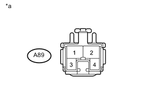
Text in Illustration *a Front view of wire harness connector
(to Stop Light Switch Assembly)
Measure the voltage according to the value(s) in the table below.
Standard Voltage Tester Connection Condition Specified Condition A89-2 - Body ground Always 11 to 14 V
-
-
for LED Type Stop Light
-
Disconnect the stop light switch assembly connector.
-
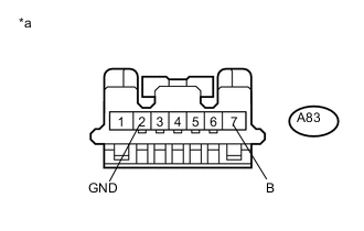
Text in Illustration *a Front view of wire harness connector
(to Stop Light Switch Assembly)
Measure the voltage according to the value(s) in the table below.
Standard Voltage Tester Connection Condition Specified Condition A83-7 (B) - A83-2 (GND) Always 11 to 14 V Standard Resistance Tester Connection Condition Specified Condition A83-2 (GND) - Body ground Always Below 1 Ω
-
NG
REPAIR OR REPLACE HARNESS OR CONNECTOR
OK
-
-
INSPECT STOP LIGHT SWITCH ASSEMBLY
-
for Bulb Type Stop Light
-
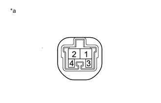
Text in Illustration *a Component without harness connected
(Stop Light Switch Assembly)
Measure the resistance according to the value(s) in the table below.
Standard Resistance Tester Connection Switch Condition Specified Condition 1 - 2 Switch pin released Below 1 Ω Switch pin pushed in 10 kΩ or higher -
Reconnect the A89 stop light switch assembly connector.
-
-
for LED Type Stop Light
-
Reconnect the stop light switch assembly connector.
-
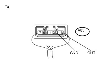
Text in Illustration *a Component with harness connected
(Stop Light Switch Assembly)
Measure the voltage according to the value(s) in the table below.
Standard Voltage Tester Connection Switch Condition Specified Condition A83-1 (OUT) - A83-2 (GND) Switch pin released 11 to 14 V Switch pin pushed in Below 1 V Result Result Proceed to OK (for Bulb Type Stop Light with Toyota Safety Sense) A OK (for Bulb Type Stop Light without Toyota Safety Sense) B OK (for LED Type Stop Light) NG C
-
B 
CHECK HARNESS AND CONNECTOR (STP TERMINAL) Click here
C
REPLACE STOP LIGHT SWITCH ASSEMBLY Click here
A
-
-
CHECK HARNESS AND CONNECTOR (SWITCH INPUT)
-
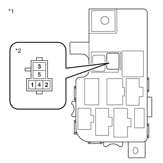
Text in Illustration *1 No. 5 Relay Block *2 STP Relay Reconnect the stop light switch assembly connector.
-
Remove the STP relay.
-
Measure the voltage according to the value(s) in the table below.
Standard Voltage Tester Connection Switch Condition Specified Condition STP relay terminal 4 - Body ground Stop light switch assembly ON (Brake pedal depressed) 11 to 14 V STP relay terminal 4 - Body ground Stop light switch assembly OFF (Brake pedal released) Below 1.5 V
NG
REPAIR OR REPLACE HARNESS OR CONNECTOR
OK
-
-
INSPECT STP RELAY
-
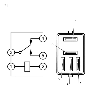
Text in Illustration *1 STP Relay Measure the resistance according to the value(s) in the table below.
Standard Resistance Tester Connection Condition Specified Condition 3 - 4 Battery voltage not applied Below 1 Ω 3 - 4 Battery voltage applied to terminal 1 and 2 10 kΩ or higher
NG
REPLACE STP RELAY
OK
-
-
CHECK HARNESS AND CONNECTOR (STP TERMINAL)
-
Disconnect the skid control ECU (brake actuator assembly) connector.
-
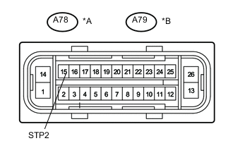
Text in Illustration *A for LHD with CVT, and RHD *B for LHD except CVT *a Front view of wire harness connector
(to Skid Control ECU (Brake Actuator Assembly))
Measure the voltage according to the value(s) in the table below.
Standard Voltage (for LHD with CVT, and RHD) Tester Connection Switch Condition Specified Condition A78-15 (STP2) - Body ground Brake pedal depressed 11 to 14 V Brake pedal released Below 1.5 V Standard Voltage (for LHD except CVT) Tester Connection Switch Condition Specified Condition A79-15 (STP2) - Body ground Brake pedal depressed 11 to 14 V Brake pedal released Below 1.5 V -
Reconnect the skid control ECU (brake actuator assembly) connector.
NG
REPAIR OR REPLACE HARNESS OR CONNECTOR
OK
-
-
RECONFIRM DTC
-
Clear the DTC Click here.
-
Check if the same DTC is output Click here.
Result Result Proceed to DTC C1249 is not output A DTC C1249 is output (for LHD) B DTC C1249 is output (for RHD) C
A
USE SIMULATION METHOD TO CHECK Click here
B
REPLACE BRAKE ACTUATOR ASSEMBLY Click here
C
REPLACE BRAKE ACTUATOR ASSEMBLY Click here
-