ANTI-LOCK BRAKE SYSTEM TS and CG Terminal Circuit
DESCRIPTION
The signal check circuit detects trouble in the sensor or switch signals which cannot be detected by the DTC check.
Connecting terminals 12 (TS) and 4 (CG) of the DLC3 starts the signal check.
WIRING DIAGRAM
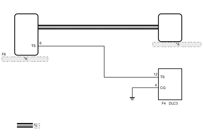
| *a | Skid Control ECU (Brake Actuator Assembly) |
| *b | Power Steering ECU Assembly |
| *c | CAN Communication Line |
PROCEDURE
-
CHECK CAN COMMUNICATION SYSTEM
-
Check if CAN communication system DTCs are output Click here.
Result Result Proceed to DTC not output A DTC output B
B 
GO TO CAN COMMUNICATION SYSTEM Click here
A 
-
-
CHECK HARNESS AND CONNECTOR (DLC3 - POWER STEERING ECU)
-
Disconnect the power steering ECU connector.
-
Measure the resistance according to the value(s) in the table below.
Standard Resistance Tester Connection Condition Specified Condition F4-12 (TS) - F6-6 (TS) Always Below 1 Ω F4-12 (TS) - Body ground Always 10 kΩ or higher
NG
REPAIR OR REPLACE HARNESS OR CONNECTOR
OK
-
-
CHECK HARNESS AND CONNECTOR (DLC3 - BODY GROUND)
-
Measure the resistance according to the value(s) in the table below.
Standard Resistance Tester Connection Condition Specified Condition F4-4 (CG) - Body ground Always Below 1 Ω Result Result Proceed to NG A OK (for LHD) B OK (for RHD) C
A
REPAIR OR REPLACE HARNESS OR CONNECTOR
B
REPLACE POWER STEERING ECU ASSEMBLY Click here
C
REPLACE POWER STEERING ECU ASSEMBLY Click here
-