ANTI-LOCK BRAKE SYSTEM Brake Warning Light Remains ON
DESCRIPTION
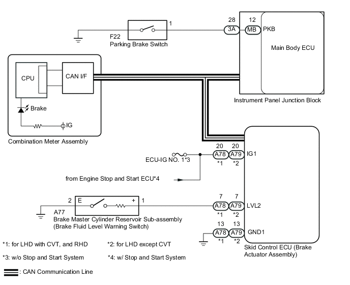
The skid control ECU (brake actuator assembly) is connected to the combination meter assembly via CAN communication.
If any of the following is detected, the brake warning light remains on:
-
The skid control ECU (brake actuator assembly) connector is disconnected from the skid control ECU.
-
The brake fluid level is insufficient.
-
The parking brake is applied.
-
EBD operation is not possible.
-
The voltage at terminal IG1 is high.
WIRING DIAGRAM
PROCEDURE
-
CHECK CAN COMMUNICATION SYSTEM
-
Check if CAN communication system DTCs are output Click here.
Result Result Proceed to DTC not output A DTC output B
B 
GO TO CAN COMMUNICATION SYSTEM Click here
A 
-
-
CHECK IF BRAKE ACTUATOR ASSEMBLY CONNECTOR IS SECURELY CONNECTED
-
Check if the skid control ECU (brake actuator assembly) connector is securely connected.
OK The connector is securely connected.
NG
CONNECT CONNECTOR TO ECU CORRECTLY
OK
-
-
CHECK HARNESS AND CONNECTOR (IG1 TERMINAL)
-
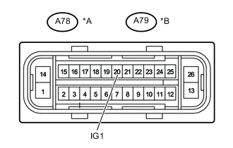
Text in Illustration *A for LHD with CVT, and RHD *B for LHD except CVT *a Front view of wire harness connector
(to Skid Control ECU (Brake Actuator Assembly))
Make sure that there is no looseness in the locking part and connecting part of the connector.
-
Disconnect the skid control ECU (brake actuator assembly) connector.
-
Turn the ignition switch to ON.
-
Measure the voltage according to the value(s) in the table below.
Standard Voltage (for LHD with CVT, and RHD) Tester Connection Switch Condition Specified Condition A78-20 (IG1) - Body ground Ignition switch ON 11 to 14 V Standard Voltage (for LHD except CVT) Tester Connection Switch Condition Specified Condition A79-20 (IG1) - Body ground Ignition switch ON 11 to 14 V -
Turn the ignition switch off.
Result Result Proceed to OK A NG (w/o Stop and Start System) B NG (w/ Stop and Start System) C
B
REPAIR OR REPLACE HARNESS OR CONNECTOR
C
GO TO STOP AND START SYSTEM Click here
A
-
-
CHECK HARNESS AND CONNECTOR (GND1 TERMINAL)
-
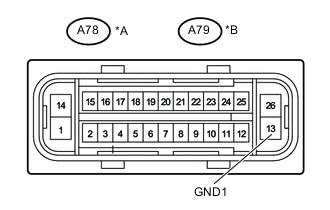
Text in Illustration *A for LHD with CVT, and RHD *B for LHD except CVT *a Front view of wire harness connector
(to Skid Control ECU (Brake Actuator Assembly))
Measure the resistance according to the value(s) in the table below.
Standard Resistance (for LHD with CVT, and RHD) Tester Connection Condition Specified Condition A78-13 (GND1) - Body ground Always Below 1 Ω Standard Resistance (for LHD except CVT) Tester Connection Condition Specified Condition A79-13 (GND1) - Body ground Always Below 1 Ω -
Reconnect the skid control ECU (brake actuator assembly) connector.
NG
REPAIR OR REPLACE HARNESS OR CONNECTOR (GND1 CIRCUIT)
OK
-
-
READ VALUE USING INTELLIGENT TESTER (PARKING BRAKE SW)
-
Turn the ignition switch off.
-
Connect the intelligent tester to the DLC3.
-
Turn the ignition switch to ON.
-
Turn the tester on.
-
Enter the following menus: Chassis / ABS/VSC/TRC / Data List.
-
According to the display on the tester, read the Data List.
ABS/VSC/TRC Tester Display Measurement Item/Range Normal Condition Diagnostic Note Parking Brake SW Parking brake switch / OFF or ON OFF: Parking brake released
ON: Parking brake applied
- -
Using the intelligent tester, check the input of the switch operation when the parking brake pedal is operated.
OK When the parking brake is operated, the display changes as shown above.
NG 
INSPECT PARKING BRAKE SWITCH Click here
OK
-
-
INSPECT BRAKE MASTER CYLINDER RESERVOIR SUB-ASSEMBLY
-
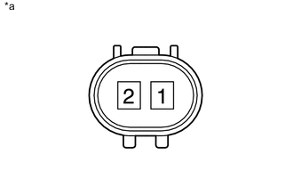
Text in Illustration *a Component without harness connected
(Brake Fluid Level Warning Switch (Brake Master Cylinder Reservoir Sub-assembly))
Remove the reservoir tank cap and strainer.
-
Disconnect the A77 brake fluid level warning switch (brake master cylinder reservoir sub-assembly) connector.
-
Measure the resistance according to the value(s) in the table below.
Tech Tips
A float is placed inside the reservoir. Its position can be changed by increasing or decreasing the brake fluid level.
Standard Resistance Tester Connection Switch Condition Specified Condition 1 - 2 Float up (Switch OFF) 10 kΩ or higher Float down (Switch ON) Below 1 Ω Tech Tips
If the result is as specified, adjust the brake fluid level to the MAX level after measuring the resistance.
Result Result Proceed to OK A NG (for LHD) B NG (for RHD) C
B
REPLACE BRAKE MASTER CYLINDER RESERVOIR SUB-ASSEMBLY Click here
C
REPLACE BRAKE MASTER CYLINDER RESERVOIR SUB-ASSEMBLY Click here
A
-
-
CHECK HARNESS AND CONNECTOR (BRAKE FLUID LEVEL WARNING SWITCH - BRAKE ACTUATOR ASSEMBLY AND BODY GROUND)
-
Disconnect the A78*1 or A79*2 skid control ECU (brake actuator assembly) connector.
-
*1: for LHD with CVT, and RHD
-
*2: for LHD except CVT
-
-
Measure the resistance according to the value(s) in the table below.
Standard Resistance (for LHD with CVT, and RHD) Tester Connection Condition Specified Condition A78-7 (LVL2) - A77-1 Always Below 1 Ω A77-2 - Body ground Always Below 1 Ω A78-7 (LVL2) or A77-1 - Body ground Always 10 kΩ or higher Standard Resistance (for LHD except CVT) Tester Connection Condition Specified Condition A79-7 (LVL2) - A77-1 Always Below 1 Ω A77-2 - Body ground Always Below 1 Ω A79-7 (LVL2) or A77-1 - Body ground Always 10 kΩ or higher
NG
REPAIR OR REPLACE HARNESS OR CONNECTOR
OK
-
-
READ VALUE USING INTELLIGENT TESTER (BRAKE WARNING LIGHT)
-
Turn the ignition switch off.
-
Connect the intelligent tester to the DLC3.
-
Turn the ignition switch to ON.
-
Turn the tester on.
-
Enter the following menus: Chassis / ABS/VSC/TRC / Data List.
-
According to the display on the tester, read the Data List.
ABS/VSC/TRC Tester Display Measurement Item/Range Normal Condition Diagnostic Note Brake Warning Light Brake warning light / OFF or ON OFF: warning light off
ON: warning light on
- -
When performing the Brake Warning Light Active Test, check Brake Warning Light in the Data List.
ABS/VSC/TRC Tester Display Test Part Control Range Diagnostic Note Brake Warning Light Brake warning light Warning light ON/OFF Observe the combination meter. Result Result Proceed to Data List Display Data List Display when Performing Active Test ON/OFF Operation ON Changes between ON and OFF A Does not change between ON and OFF (for LHD) B Does not change between ON and OFF (for RHD) C OFF Changes between ON and OFF A Does not change between ON and OFF (for LHD) B Does not change between ON and OFF (for RHD) C
A
GO TO METER / GAUGE SYSTEM Click here
B
REPLACE BRAKE ACTUATOR ASSEMBLY Click here
C
REPLACE BRAKE ACTUATOR ASSEMBLY Click here
-
-
INSPECT PARKING BRAKE SWITCH
-
Disconnect the F22 parking brake switch connector.
-
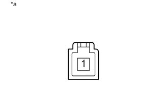
Text in Illustration *a Component without harness connected
(Parking Brake Switch)
Measure the resistance according to the value(s) in the table below.
Standard Resistance Tester Connection Switch Condition Specified Condition 1 - Body ground Parking brake switch on
(Switch pin not pushed in)
Below 1 Ω Parking brake switch off
(Switch pin pushed in)
10 kΩ or higher
NG
REPLACE PARKING BRAKE SWITCH Click here
OK
-
-
CHECK HARNESS AND CONNECTOR (INSTRUMENT PANEL JUNCTION BLOCK - PARKING BRAKE SWITCH)
-
Disconnect the 3A instrument panel junction block assembly connector.
-
Disconnect the F22 parking brake switch connector.
-
Measure the resistance according to the value(s) in the table below.
Standard Resistance Tester Connection Condition Specified Condition 3A-28 (PKB) - F22-1 Always Below 1 Ω 3A-28 (PKB) or F22-1 - Body ground Always 10 kΩ or higher
NG
REPAIR OR REPLACE HARNESS OR CONNECTOR
OK
-
-
INSPECT INSTRUMENT PANEL JUNCTION BLOCK ASSEMBLY
-
Remove the main body ECU (multiplex network body ECU) from the instrument panel junction block assembly.
-
Disconnect the instrument panel junction block assembly connector.
-
Measure the resistance according to the value(s) in the table below.
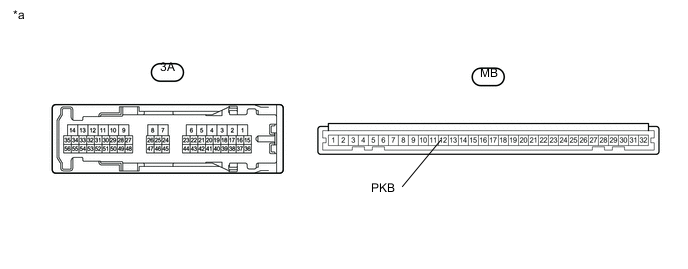
Text in Illustration *a Component without harness connected
(Instrument Panel Junction Block Assembly)
- - Standard Resistance Tester Connection Condition Specified Condition 3A-28 - MB-12 (PKB) Always Below 1 Ω -
Reconnect the instrument panel junction block assembly connector.
-
Reinstall the main body ECU (multiplex network body ECU) to the instrument panel junction block assembly.
OK
REPLACE MAIN BODY ECU (MULTIPLEX NETWORK BODY ECU)
NG
REPLACE INSTRUMENT PANEL JUNCTION BLOCK ASSEMBLY
-