ANTI-LOCK BRAKE SYSTEM, Diagnostic DTC:C1241

| DTC Code | DTC Name |
|---|---|
| C1241 | Low Power Supply Voltage Malfunction |
DESCRIPTION
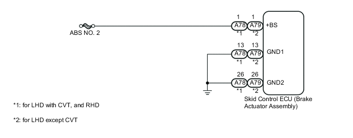
When there is an abnormality in the power supply circuit of the skid control ECU (brake actuator assembly), the skid control ECU sets a DTC and the operation is prohibited by the fail-safe function. This DTC is set when the voltage supplied to terminal +BS is outside the DTC detection threshold, due to abnormalities of the battery, power source circuits or charging circuits such as the alternator circuit.
The fail-safe function is canceled when the voltage to terminals IG1 and +BS returns to normal.
| DTC No. | DTC Detection Condition | Trouble Area |
|---|---|---|
| C1241 | When any of following conditions detected:
|
|
WIRING DIAGRAM
CAUTION / NOTICE / HINT
Note
Inspect the fuses for circuits related to this system before performing the following inspection procedure.
PROCEDURE
-
INSPECT BATTERY
-
Check the battery voltage.
Standard voltage 11 to 14 V Result Result Proceed to OK A NG (for 1KR-FE) B NG (for 1NR-FE) C NG (for 1ND-TV) D
B 
GO TO CHARGING SYSTEM Click here
C
GO TO CHARGING SYSTEM Click here
D
GO TO CHARGING SYSTEM Click here
A 
-
-
CHECK HARNESS AND CONNECTOR (BATTERY - SKID CONTROL ECU - BODY GROUND)
-
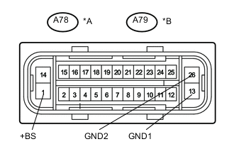
Text in Illustration *A for LHD with CVT, and RHD *B for LHD except CVT *a Front view of wire harness connector
(to Skid Control ECU)
Disconnect the skid control ECU connector.
-
Measure the voltage according to the value(s) in the table below.
Standard Voltage (for LHD with CVT, and RHD) Tester Connection Condition Specified Condition A78-1 (+BS) - Body ground Always 11 to 14 V Standard Voltage (for LHD except CVT) Tester Connection Condition Specified Condition A79-1 (+BS) - Body ground Always 11 to 14 V -
Measure the resistance according to the value(s) in the table below.
Standard Resistance (for LHD with CVT, and RHD) Tester Connection Condition Specified Condition A78-13 (GND1) - Body ground Always Below 1 Ω A78-26 (GND2) - Body ground Always Below 1 Ω Standard Resistance (for LHD except CVT) Tester Connection Condition Specified Condition A79-13 (GND1) - Body ground Always Below 1 Ω A79-26 (GND2) - Body ground Always Below 1 Ω
NG
REPAIR OR REPLACE HARNESS OR CONNECTOR
OK
-
-
RECONFIRM DTC
-
Clear the DTC Click here.
-
Drive the vehicle at 10 km/h (6 mph) or more for several seconds.
-
Check if the same DTC is output Click here.
Result Result Proceed to DTC C1241 is not output A DTC C1241 is output (for LHD) B DTC C1241 is output (for RHD) C
A
CHECK FOR INTERMITTENT PROBLEMS Click here
B
REPLACE BRAKE ACTUATOR ASSEMBLY Click here
C
REPLACE BRAKE ACTUATOR ASSEMBLY Click here
-