ANTI-LOCK BRAKE SYSTEM, Diagnostic DTC:C1271, C1272, C1275, C1276, C1330, C1331, C1464, C1465

| DTC Code | DTC Name |
|---|---|
| C1271 | Low Output Signal of Front Speed Sensor RH (Test Mode DTC) |
| C1272 | Low Output Signal of Front Speed Sensor LH (Test Mode DTC) |
| C1275 | Abnormal Change in Output Signal of Front Speed Sensor RH (Test Mode DTC) |
| C1276 | Abnormal Change in Output Signal of Front Speed Sensor LH (Test Mode DTC) |
| C1330 | Open in Front Speed Sensor RH |
| C1331 | Open in Front Speed Sensor LH |
| C1464 | Front Speed Sensor RH |
| C1465 | Front Speed Sensor LH |
DESCRIPTION
The speed sensors detect the wheel speeds and send appropriate signals to the skid control ECU.
Speed sensor rotors have rows of alternating N and S magnetic poles, and their magnetic fields change as the rotors turn.
Each speed sensor detects that magnetic change and sends a pulse signal to the skid control ECU (brake actuator assembly).
Tech Tips
When the connectors between the speed sensor and skid control ECU are connected, the following waveform is output.
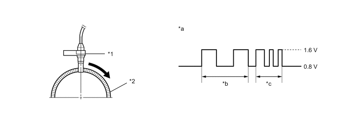
| *1 | Speed Sensor | *2 | Speed Sensor Rotor |
| *a | Waveform (Reference): Between Speed Sensor (-) and Body Ground |
*b | Low speed |
| *c | High speed | - | - |
| DTC No. | DTC Detection Condition | Trouble Area |
|---|---|---|
| C1330 C1331 |
Open in front speed sensor circuit continues for 0.15 seconds or more. |
|
| C1464 C1465 |
When any of following conditions detected:
|
|
| DTC No. | DTC Detection Condition | Trouble Area |
|---|---|---|
| C1271 C1272 |
Detected only during test mode. |
|
| C1275 C1276 |
Detected only during test mode. |
|
Tech Tips
-
DTCs C1330 and C1464 relate to the front speed sensor RH.
-
DTCs C1331 and C1465 relate to the front speed sensor LH.
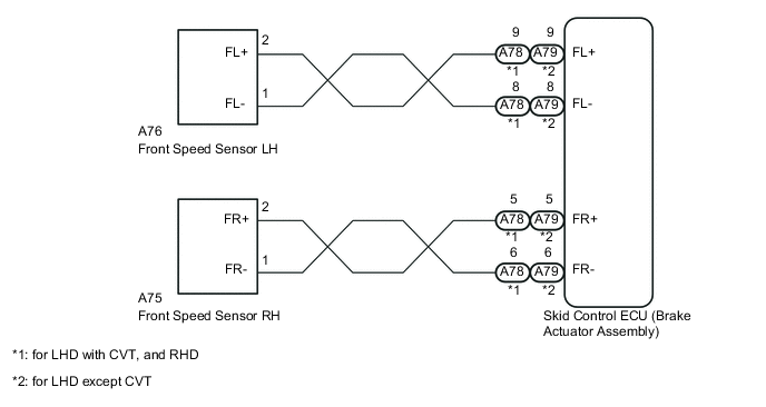
WIRING DIAGRAM
CAUTION / NOTICE / HINT
Tech Tips
Check the speed sensor signal in test mode after cleaning or replacement Click here.
PROCEDURE
-
READ VALUE USING INTELLIGENT TESTER (FR WHEEL SPEED AND FL WHEEL SPEED)
-
Connect the intelligent tester to the DLC3.
-
Start the engine.
-
Turn the tester on.
-
Entry the following menu: Chassis / ABS/VSC/TRC / Data List.
-
In accordance with the display on the tester, read the Data List.
ABS/VSC/TRC Tester Display Measurement Item/Range Normal Condition Diagnostic Note FR Wheel Speed Wheel speed sensor (FR) reading: min.: 0 km/h (0 mph), max.: 326 km/h (202 mph) Similar to speed indicated on speedometer When driving at constant speed: No large fluctuations FL Wheel Speed Wheel speed sensor (FL) reading: min.: 0 km/h (0 mph), max.: 326 km/h (202 mph) Similar to speed indicated on speedometer When driving at constant speed: No large fluctuations -
Check that there is no significant difference between the speed value displayed on the intelligent tester and the speed value displayed on the speedometer when driving the vehicle.
OK There is almost no difference in the displayed speed values. Tech Tips
There is a tolerance of +/- 10% in the speedometer indication.
NG 
CHECK FRONT SPEED SENSOR INSTALLATION Click here
OK 
-
-
PERFORM TEST MODE INSPECTION (SIGNAL CHECK)
-
Perform a Test Mode inspection and check for DTCs Click here.
OK No DTC output.
NG
CHECK FRONT SPEED SENSOR INSTALLATION Click here
OK
-
-
RECONFIRM DTC
-
Clear the DTC(s) Click here.
-
Start the engine.
-
Drive the vehicle at a speed of 20 km/h (12 mph) or more for at least 60 seconds.
-
Check if the same DTC(s) is output Click here.
Result Result Proceed to DTC not output A DTCs C1330, C1331, C1464 and C1465 are not output B
A 
CHECK FOR INTERMITTENT PROBLEMS Click here
B
REPLACE FRONT SPEED SENSOR Click here
-
-
CHECK FRONT SPEED SENSOR INSTALLATION
-
Check that the speed sensor installation bolt is tightened properly.
OK The installation bolt is tightened properly. - Torque:
- 8.0 N*m { 82 kgf*cm, 71 in.*lbf }
NG
TIGHTEN BOLT PROPERLY
OK
-
-
CHECK FRONT SPEED SENSOR
-
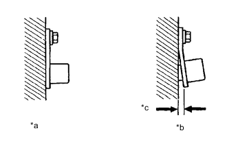
Text In Illustration *a Normal *b Abnormal *c Clearance Visually check the speed sensor for deformation and damage.
OK No deformation or damage. There is no gap between the sensor and front steering knuckle. Note
Check the speed sensor signal after cleaning or replacement Click here.
NG
REPLACE FRONT SPEED SENSOR Click here
OK
-
-
CHECK SPEED SENSOR TIP
-
Remove the speed sensor Click here.
-
Check the sensor tip.
OK No scratches or foreign matter on the sensor tip.
NG
CLEAN OR REPLACE SPEED SENSOR
OK
-
-
INSPECT FRONT SPEED SENSOR ROTOR
-
Remove the front axle hub sub-assembly Click here.
-
Check the speed sensor rotor.
OK No scratches, oil, or foreign matter on the rotors. Note
Check the speed sensor signal after cleaning or replacement Click here.
Tech Tips
If the front axle hub assembly needs to be replaced, replace it together with the front drive outboard joint shaft assembly.
-
Reinstall the front axle hub assembly Click here.
NG
CLEAN OR REPLACE FRONT SPEED SENSOR ROTOR
OK
-
-
CHECK HARNESS AND CONNECTOR (SKID CONTROL ECU - FRONT SPEED SENSOR)
-
Confirm that the skid control ECU connector and speed sensor connector are properly connected.
-
Disconnect the skid control ECU connector and the front speed sensor connector.
-
Inspect both the connector case and the terminal for deformation and corrosion.
OK No deformation or corrosion. -
Measure the resistance according to the value(s) in the table below.
Standard Resistance (for LHD with CVT, and RHD) Tester Connection Condition Specified Condition A78-9 (FL+) - A76-2 (FL+) Always Below 1 Ω A78-8 (FL-) - A76-1 (FL-) Always Below 1 Ω A78-5 (FR+) - A75-2 (FR+) Always Below 1 Ω A78-6 (FR-) - A75-1 (FR-) Always Below 1 Ω Standard Resistance (for LHD except CVT) Tester Connection Condition Specified Condition A79-9 (FL+) - A76-2 (FL+) Always Below 1 Ω A79-8 (FL-) - A76-1 (FL-) Always Below 1 Ω A79-5 (FR+) - A75-2 (FR+) Always Below 1 Ω A79-6 (FR-) - A75-1 (FR-) Always Below 1 Ω
NG
REPAIR OR REPLACE HARNESS OR CONNECTOR
OK
-
-
INSPECT FRONT SPEED SENSOR (INPUT VOLTAGE)
-
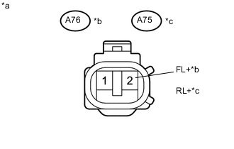
Text in Illustration *a Front view of wire harness connector
(to Speed Sensor RH/LH)
*b LH *c RH Turn the ignition switch to ON.
-
Measure the voltage according to the value(s) in the table below.
Standard Voltage Tester Connection Switch Condition Specified Condition A76-2 (FL+) - Body ground Ignition switch ON 7.5 to 15 V A75-2 (FR+) - Body ground Ignition switch ON 7.5 to 15 V Result Result Proceed to OK A NG (for LHD) B NG (for RHD) C
B
REPLACE BRAKE ACTUATOR ASSEMBLY Click here
C
REPLACE BRAKE ACTUATOR ASSEMBLY Click here
A
-
-
RECONFIRM DTC
-
Clear the DTC(s) Click here.
-
Start the engine.
-
Drive the vehicle at a speed of 20 km/h (12 mph) or more for at least 60 seconds.
-
Check if the same DTC(s) is output Click here.
Result Result Proceed to DTC output A DTC not output B
B
CHECK FOR INTERMITTENT PROBLEMS Click here
A
-
-
REPLACE FRONT SPEED SENSOR
-
Replace the front speed sensor Click here.
NEXT
-
-
RECONFIRM DTC
-
Clear the DTC(s) Click here.
-
Start the engine.
-
Drive the vehicle at a speed of 20 km/h (12 mph) or more for at least 60 seconds.
-
Check if the same DTC(s) is output Click here.
Result Result Proceed to DTC not output A DTC output (for LHD) B DTC output (for RHD) C
A
END
B
REPLACE BRAKE ACTUATOR ASSEMBLY Click here
C
REPLACE BRAKE ACTUATOR ASSEMBLY Click here
-