ANTI-LOCK BRAKE SYSTEM TEST MODE PROCEDURE

Tech Tips
-
By switching the skid control ECU from normal mode to test mode, abnormality detection sensitivity is enhanced and troubleshooting can be conducted efficiently.
-
Perform a sensor check in test mode after the speed sensor or sensor rotor has been repaired or replaced.
-
If the ignition switch is turned from on to ACC or off during test mode, DTCs related to the signal check function will be erased.
-
During test mode, the skid control ECU stores all DTCs related to the signal check function, and the DTCs are erased if normality is confirmed. Any remaining DTCs are those indicating abnormalities that were found.
-
TEST MODE (SIGNAL CHECK) PROCEDURE (for Using an Intelligent Tester)
-
Turn the ignition switch off.
-
Check that the steering wheel is in the straight-ahead position.
-
Check that the shift lever is in neutral and apply the parking brake.
Tech Tips
Application of the parking brake is not included in the conditions for the commencement of test mode.
-
Connect the intelligent tester to the DLC3.
-
Turn the ignition switch to ON.
-
Turn the tester on.
-
Switch the skid control ECU to test mode using the intelligent tester.
Entry the following menu: Chassis / ABS/VSC/TRC / Utility / Signal Check.
-
Check that the ABS warning light blinks.
-
-
TEST MODE (SIGNAL CHECK) PROCEDURE (for Using SST Check Wire)
-
Turn the ignition switch off.
-
Check that the steering wheel is in the straight-ahead position.
-
Check that the shift lever is in neutral and apply the parking brake.
Tech Tips
Application of the parking brake is not included in the conditions for the commencement of test mode.
-
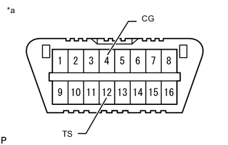
Text in Illustration *a Front view of DLC3 Using SST, connect terminals TS and CG of the DLC3.
- SST
- 09843-18040
-
Turn the ignition switch to ON.
-
Check that the ABS warning light blinks.
-
-
SPEED SENSOR CHECK
-
Check that the ABS warning light is blinking.
-
Check the speed sensor signal.
-
Drive the vehicle straight forward at a speed of 45 km/h (28 mph) or more for several seconds.
-
Check that the ABS warning light goes off.
Tech Tips
-
The speed sensor check may not be completed if the sensor check is started with the steering wheel turned or one or more wheels spinning.
-
If the speed sensor check is commenced while the steering wheel is turned, the ABS warning light may come on after the low speed check is finished.
-
The ABS warning light comes on immediately when an abnormality is detected.
-
When the speed sensor signal is normal, the ABS warning light turns off while driving at 45 km/h (28 mph) or more and blinks in the test mode pattern while the vehicle is stationary.
-
Do not drive the vehicle at a speed of 80 km/h (50 mph) or more after the ABS warning light turns off, because test mode DTCs are set again when the vehicle speed exceeds 80 km/h (50 mph).
-
If the vehicle is driven on extremely rough or bumpy roads, sensor signal check may fail and middle speed check DTCs may not be deleted. In such cases, stop the vehicle and drive it again to resume the speed sensor check.
-
-
Stop the vehicle.
-
-
-
END OF SENSOR CHECK
-
When the sensor check is successfully completed, the ABS warning light blinks in the test mode pattern when the vehicle is stopped, and goes off when the vehicle is driven.
Note
If the sensor check is not completed, the ABS warning light blinks even while the vehicle is driving and the ABS does not operate.
-
-
READ SIGNAL CHECK FUNCTION DTCs (for Using Intelligent Tester)
-
Read the DTC(s) by following the instructions on the tester screen.
-
-
READ SENSOR SIGNAL CHECK FUNCTION DTCs (for Using SST Check Wire)
-
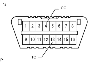
Text in Illustration *a Front view of DLC3 Using SST, connect terminals TC and CG of the DLC3.
- SST
- 09843-18040
-
Turn the ignition switch to ON.
-
Read the number of blinks of the ABS warning light.
Tech Tips
-
When the system is operating correctly, each light will blink continuously in a pattern of 0.25 seconds on, and then 0.25 seconds off.
-
When one DTC is output, each light will output the same code at 4 second intervals (for example, code 21 would be output as 2 flashes, a 1.5 second pause, and then 1 flash).
-
When 2 or more DTCs are output, each light will output a different code at 2.5 second intervals, and when all codes have been output, there will be a 4 second pause and the sequence will repeat.
-
When multiple codes are stored, they are output in order starting with the lowest DTC number
-
-
After the check, disconnect the SST from terminals TC and CG of the DLC3.
-
Turn the ignition switch off.
-
-
SENSOR SIGNAL CHECK FUNCTION DTCs
ABS Sensor DTC No. Detection Item Trouble Area Intelligent Tester Display ABS Warning Light Display C1271 71 Low output signal of front speed sensor RH
-
Front speed sensor RH
-
Speed sensor circuit
-
Sensor installation
C1272 72 Low output signal of front speed sensor LH
-
Front speed sensor LH
-
Speed sensor circuit
-
Sensor installation
C1273 73 Low output signal of rear speed sensor RH
-
Rear speed sensor RH
-
Speed sensor circuit
-
Sensor installation
C1274 74 Low output signal of rear speed sensor LH
-
Rear speed sensor LH
-
Speed sensor circuit
-
Sensor installation
C1275 75 Abnormal change in output signal of front speed sensor RH
-
Sensor installation
-
Speed sensor rotor
-
Foreign matter on sensor tip or sensor rotor
C1276 76 Abnormal change in output signal of front speed sensor LH
-
Sensor installation
-
Speed sensor rotor
-
Foreign matter on sensor tip or sensor rotor
C1277 77 Abnormal change in output signal of rear speed sensor RH
-
Sensor installation
-
Speed sensor rotor
-
Foreign matter on sensor tip or sensor rotor
C1278 78 Abnormal change in output signal of rear speed sensor LH
-
Sensor installation
-
Speed sensor rotor
-
Foreign matter on sensor tip or sensor rotor
Tech Tips
-
The DTCs in this table are only output in test mode.
-
Detection of DTCs from C1271/71 to C1274/74 is completed before the vehicle speed reaches 5 km/h (3 mph).
-
Detection of DTCs from C1275/75 to C1278/78 is completed before the vehicle speed reaches 45 km/h (28 mph).
-
C1271/71 - C1274/74: Speed sensor output from only one wheel is extremely low despite the other wheel speed outputs reaching 5 km/h (3 mph).
-