ECD SYSTEM(w/ DPF), Diagnostic DTC:P0641
| DTC Code | DTC Name |
|---|---|
| P0641 | Sensor Reference Voltage "A" Circuit / Open |
DESCRIPTION
Refer to DTC P0107 Click here.
Refer to DTC P2122 Click here.
Refer to DTC P2454 Click here.
| DTC Detection Drive Pattern | DTC Detection Condition | Trouble Area |
|---|---|---|
| Ignition switch ON | Power voltages (5 V as standard) supplied from ECM to accelerator pedal position sensor, diesel turbo pressure sensor and differential pressure sensor are lower or higher than appropriate thresholds. (1 trip detection logic) |
|
WIRING DIAGRAM
Refer to DTC P0107 Click here.
Refer to DTC P2122 Click here.
Refer to DTC P2454 Click here.
CAUTION / NOTICE / HINT
Note
When replacing the ECM, the ECM needs Registration and Initialization Click here.
Tech Tips
-
When the ECM must be replaced, before replacing the ECM, perform the "Learning Values Save" function using the GTS. Then after installing the new ECM, perform all of the initialization/registrations for the "Learning Values Write" function by following the instructions shown on the GTS display.
-
Read freeze frame data using the GTS. Freeze frame data records the engine condition when malfunctions are detected. When troubleshooting, freeze frame data can help determine if the vehicle was moving or stationary, if the engine was warmed up or not, and other data from the time the malfunction occurred.
PROCEDURE
-
CHECK HARNESS AND CONNECTOR (ACCELERATOR PEDAL SENSOR ASSEMBLY - ECM)
-
Disconnect the A36 accelerator pedal sensor assembly connector.
-
Disconnect the A108 ECM connector.
-
Measure the resistance according to the value(s) in the table below.
Standard Resistance Tester Connection Condition Specified Condition A36-4 (VCPA) or A108-27 (VCPA) - Body ground Always 10 kΩ or higher A36-6 (VPA) or A108-42 (VPA) - Body ground Always 10 kΩ or higher A36-5 (EPA) or A108-22 (EPA) - Body ground Always 10 kΩ or higher A36-1 (VCP2) or A108-28 (VCP2) - Body ground Always 10 kΩ or higher A36-3 (VPA2) or A108-43 (VPA2) - Body ground Always 10 kΩ or higher A36-2 (EPA2) or A108-23 (EPA2) - Body ground Always 10 kΩ or higher
NG 
REPAIR OR REPLACE HARNESS OR CONNECTOR Click here
OK 
-
-
CHECK TERMINAL VOLTAGE (VC VOLTAGE)
-
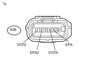
Text in Illustration *a Front view of wire harness connector
(to Accelerator Pedal Sensor Assembly)
Disconnect the accelerator pedal sensor assembly connector.
-
Turn the ignition switch to ON.
-
Measure the voltage according to the value(s) in the table below.
Standard Voltage Tester Connection Switch Condition Specified Condition A36-4 (VCPA) - A36-5 (EPA) Ignition switch ON 4.5 to 5.5 V A36-1 (VCP2) - A36-2 (EPA2) Ignition switch ON 4.5 to 5.5 V
NG
REPLACE ECM Click here
OK
-
-
CHECK HARNESS AND CONNECTOR (DIFFERENTIAL PRESSURE SENSOR - ECM)
-
Disconnect the B43 differential pressure sensor connector.
-
Disconnect the B104 ECM connector (for LHD).
-
Disconnect the B103 ECM connector (for RHD).
-
Measure the resistance according to the value(s) in the table below.
Standard Resistance for LHD Tester Connection Condition Specified Condition B43-2 (PEX) or B104-86 (PEX) - Body ground Always 10 kΩ or higher B43-3 (VC) or B104-71 (VCPX) - Body ground Always 10 kΩ or higher B43-1 (E2) or B104-118 (EPEX) - Body ground Always 10 kΩ or higher for RHD Tester Connection Condition Specified Condition B43-2 (PEX) or B103-86 (PEX) - Body ground Always 10 kΩ or higher B43-3 (VC) or B103-71 (VCPX) - Body ground Always 10 kΩ or higher B43-1 (E2) or B103-118 (EPEX) - Body ground Always 10 kΩ or higher
NG
REPAIR OR REPLACE HARNESS OR CONNECTOR Click here
OK
-
-
CHECK TERMINAL VOLTAGE (VC VOLTAGE)
-
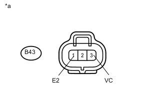
Text in Illustration *a Front view of wire harness connector
(to Differential Pressure Sensor)
Disconnect the differential pressure sensor connector.
-
Turn the ignition switch to ON.
-
Measure the voltage according to the value(s) in the table below.
Standard Voltage Tester Connection Switch Condition Specified Condition B43-3 (VC) - B43-1 (E2) Ignition switch ON 4.5 to 5.5 V
NG
REPLACE ECM Click here
OK
-
-
CHECK HARNESS AND CONNECTOR (DIESEL TURBO PRESSURE SENSOR - ECM)
-
Disconnect the B49 diesel turbo pressure sensor connector.
-
Disconnect the B104 ECM connector (for LHD).
-
Disconnect the B103 ECM connector (for RHD).
-
Measure the resistance according to the value(s) in the table below.
Standard Resistance for LHD Tester Connection Condition Specified Condition B49-2 (PIM) or B104-78 (PIM) - Body ground Always 10 kΩ or higher B49-3 (VC) or B104-63 (VPIM) - Body ground Always 10 kΩ or higher B49-1 (E) or B104-110 (EPIM) - Body ground Always 10 kΩ or higher for RHD Tester Connection Condition Specified Condition B49-2 (PIM) or B103-78 (PIM) - Body ground Always 10 kΩ or higher B49-3 (VC) or B103-63 (VPIM) - Body ground Always 10 kΩ or higher B49-1 (E) or B103-110 (EPIM) - Body ground Always 10 kΩ or higher
NG
REPAIR OR REPLACE HARNESS OR CONNECTOR Click here
OK
-
-
CHECK TERMINAL VOLTAGE (VC VOLTAGE)
-
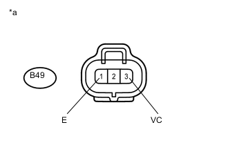
Text in Illustration *a Front view of wire harness connector
(to Turbo Pressure Sensor)
Disconnect the diesel turbo pressure sensor connector.
-
Turn the ignition switch to ON.
-
Measure the voltage according to the value(s) in the table below.
Standard Voltage Tester Connection Switch Condition Specified Condition B49-3 (VC) - B49-1 (E) Ignition switch ON 4.5 to 5.5 V
NG
REPLACE ECM Click here
OK
-
-
REPLACE DIESEL TURBO PRESSURE SENSOR
-
Replace the diesel turbo pressure sensor Click here.
NEXT
-
-
CHECK WHETHER DTC OUTPUT RECURS (DTC P0641)
-
Connect the GTS to the DLC3.
-
Turn the ignition switch to ON.
-
Turn the GTS on.
-
Clear the DTCs Click here.
-
Turn the ignition switch off and wait for 30 seconds or more.
-
Turn the ignition switch to ON.
-
Enter the following menus: Powertrain / Engine and ECT / Trouble Codes.
-
Read the DTC.
Result Result Proceed to DTC is not output A DTC P0641 is output B
A 
END
B
-
-
REPLACE DIFFERENTIAL PRESSURE SENSOR
-
Replace the differential pressure sensor Click here.
NEXT
-
-
CHECK WHETHER DTC OUTPUT RECURS (DTC P0641)
-
Connect the GTS to the DLC3.
-
Turn the ignition switch to ON.
-
Turn the GTS on.
-
Clear the DTCs Click here.
-
Turn the ignition switch off and wait for 30 seconds or more.
-
Turn the ignition switch to ON.
-
Enter the following menus: Powertrain / Engine and ECT / Trouble Codes.
-
Read the DTC.
Result Result Proceed to DTC is not output A DTC P0641 is output B
A
END
B
-
-
REPLACE ACCELERATOR PEDAL SENSOR ASSEMBLY
-
Replace the accelerator pedal sensor assembly Click here.
NEXT
CONFIRM WHETHER MALFUNCTION HAS BEEN SUCCESSFULLY REPAIRED Click here
-
-
REPAIR OR REPLACE HARNESS OR CONNECTOR
NEXT
CONFIRM WHETHER MALFUNCTION HAS BEEN SUCCESSFULLY REPAIRED Click here
-
REPLACE ECM
-
Replace the ECM Click here.
NEXT
-
-
CONFIRM WHETHER MALFUNCTION HAS BEEN SUCCESSFULLY REPAIRED
-
Connect the GTS to the DLC3.
-
Turn the ignition switch to ON.
-
Turn the GTS on.
-
Clear the DTCs Click here.
-
Turn the ignition switch off and wait for 30 seconds or more.
-
Turn the ignition switch to ON.
-
Enter the following menus: Powertrain / Engine and ECT / Trouble Codes.
-
Confirm that the DTC is not output again.
NEXT
END
-