| DTC Code | DTC Name |
|---|---|
| Fuel Injector Circuit |
DESCRIPTION
The Fuel injectors are installed in the intake port, and inject fuel into the cylinders based on the signals from the ECM.
CAUTION / NOTICE / HINT
-
Inspect the fuses for circuits related to this system before performing the following inspection procedure.
-
Perform electronic throttle learning after replacing the ECM (Click here).
PROCEDURE
- Click here
INSPECT FUEL INJECTOR ASSEMBLY (POWER SOURCE)
-
Disconnect the fuel injector assembly connector.
-
Turn the ignition switch to ON.
-
Measure the voltage according to the value(s) in the table below.
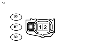
Standard Voltage Tester Connection Switch Condition Specified Condition B5-2 - Body ground Ignition switch ON 11 to 14 V B7-2 - Body ground Ignition switch ON 11 to 14 V B9-2 - Body ground Ignition switch ON 11 to 14 V Table 1. Text in Illustration *a Front view of wire harness connector
(to Fuel Injector Assembly)
- OKClick here
- NGClick here
-
- Click here
INSPECT FUEL INJECTOR ASSEMBLY (INJECTION AND VOLUME)
-
Check the fuel injector injection and volume (Click here).
- OKClick here
- NG
REPLACE FUEL INJECTOR ASSEMBLY (Click here)
-
- Click here
CHECK HARNESS AND CONNECTOR (FUEL INJECTOR ASSEMBLY - ECM)
-
Disconnect the ECM connector.
-
Disconnect the fuel injector assembly connector.
-
Measure the resistance according to the value(s) in the table below.
Standard Resistance Tester Connection Condition Specified Condition B5-1 - B87-45 (#10) Always Below 1 Ω B7-1 - B87-46 (#20) Always Below 1 Ω B9-1 - B87-67 (#30) Always Below 1 Ω B5-1 or B87-45 (#10) - Body ground Always 10 kΩ or higher B7-1 or B87-46 (#20) - Body ground Always 10 kΩ or higher B9-1 or B87-67 (#30) - Body ground Always 10 kΩ or higher
- OK
PROCEED TO NEXT SUSPECTED AREA SHOWN IN PROBLEM SYMPTOMS TABLE (Click here)
- NG
REPAIR OR REPLACE HARNESS OR CONNECTOR
-
- Click here
CHECK HARNESS AND CONNECTOR (NO. 1 INTEGRATION RELAY - FUEL INJECTOR ASSEMBLY)
-
Remove the No. 1 integration relay from the engine room relay block.
-
Disconnect the fuel injector assembly connector.
-
Measure the resistance according to the value(s) in the table below.
Standard Resistance Tester Connection Condition Specified Condition B5-2 - 1E-4 Always Below 1 Ω B7-2 - 1E-4 Always Below 1 Ω B9-2 - 1E-4 Always Below 1 Ω B5-2 or 1E-4 - Body ground Always 10 kΩ or higher B7-2 or 1E-4 - Body ground Always 10 kΩ or higher B9-2 or 1E-4 - Body ground Always 10 kΩ or higher
- OK
CHECK ECM POWER SOURCE CIRCUIT (Click here)
- NG
REPAIR OR REPLACE HARNESS OR CONNECTOR
-