SFI SYSTEM ECM Back-up Power Source Circuit
DESCRIPTION
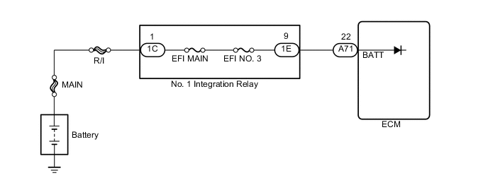
The battery supplies electricity to terminal BATT of the ECM even when the ignition switch is off. This electricity allows the ECM to store DTC histories, freeze frame data, fuel trim values and other data.
WIRING DIAGRAM
CAUTION / NOTICE / HINT
Note
-
Inspection the fuses for circuits related to this system before performing the following inspection procedure.
-
Perform electronic throttle learning after replacing the ECM Click here.
-
After turning ignition switch off, waiting time may be required before disconnecting the cable from the negative (-) battery terminal. Therefore, make sure to read the disconnecting the cable from the negative (-) battery terminal notices before proceeding with work Click here.
PROCEDURE
-
INSPECT BATTERY
-
Check that the battery is not depleted.
OK Battery is not depleted.
NG 
REPLACE BATTERY
OK 
-
-
CHECK BATTERY TERMINAL
-
Check that the battery terminals are not loose or corroded Click here.
OK Battery terminals are not loose or corroded.
NG
REPAIR OR REPLACE BATTERY TERMINAL
OK
-
-
INSPECT NO. 1 INTEGRATION RELAY
-
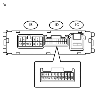
Text in Illustration *a Compartment without harness connected
(No. 1 Integration Relay)
Remove the No. 1 integration relay from engine room relay block.
-
Measure the resistance according to the value(s) in the table below.
Standard Resistance Tester Connection Condition Specified Condition 1C-1 - 1E-9 Always Below 1 Ω
NG
REPLACE NO. 1 INTEGRATION RELAY Click here
OK
-
-
CHECK HARNESS AND CONNECTOR (NO.1 INTEGRATION RELAY - ECM)
-
Remove the No. 1 integration relay from engine room relay block.
-
Disconnect the ECM connector.
-
Measure the resistance according to the value(s) in the table below.
Standard Resistance Tester Connection Condition Specified Condition 1E-9 - A71-22 (BATT) Always Below 1 Ω 1E-9 or A71-22 (BATT) - Body ground Always 10 kΩ or higher
NG
REPAIR OR REPLACE HARNESS OR CONNECTOR
OK
-
-
CHECK HARNESS AND CONNECTOR (NO. 1 INTEGRATION RELAY - BATTERY)
-
Disconnect the negative battery terminal.
-
Disconnect the positive battery terminal.
-
Remove the No. 1 integration relay from engine room relay block.
-
Measure the resistance according to the value(s) in the table below.
Standard Resistance Tester Connection Condition Specified Condition 1C-1 - Battery positive terminal Always Below 1 Ω 1C-1 or Battery positive terminal - Body ground Always 10 kΩ or higher
OK
REPLACE ECM Click here
NG
REPAIR OR REPLACE HARNESS OR CONNECTOR
-