SFI SYSTEM, Diagnostic DTC:P0420
| DTC Code | DTC Name |
|---|---|
| P0420 | Catalyst System Efficiency Below Threshold (Bank 1) |
DESCRIPTION
This vehicle has two heated oxygen sensors. One is located in front of the Three-Way Catalytic Converter (TWC), and the other is mounted behind the TWC. The output signals of the sensors are converted into waveforms inside the ECM. The heated oxygen sensor is used by the ECM to monitor the air fuel ratio, and its signal prompts the ECM to perform air fuel ratio feedback control. As a result, the air fuel ratio is balanced, and the waveform of the heated oxygen sensor regularly oscillates between rich and lean. To determine whether or not the TWC performance has deteriorated, the ECM compares the waveforms of the heated oxygen sensor and No. 2 heated oxygen sensor. While the TWC is functioning normally, the waveform of the No. 2 heated oxygen sensor fluctuates between rich and lean more slowly than the heated oxygen sensor waveform. When the No. 2 heated oxygen sensor waveform frequently fluctuates, it indicates that the TWC performance has deteriorated.
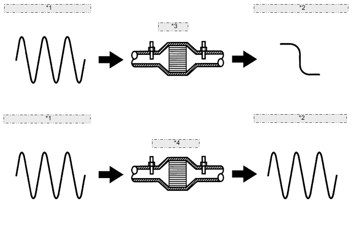
| *1 | Waveform of Heated Oxygen Sensor (in front of TWC) |
| *2 | Waveform of No. 2 Heated Oxygen Sensor (behind TWC) |
| *3 | Normal TWC |
| *4 | Deteriorated TWC |
| DTC No. | DTC Detection Condition | Trouble Area |
|---|---|---|
| P0420 | After engine and TWC are warmed up, and while vehicle is driven within predetermined engine speed (3 trip detection logic). |
|
Tech Tips
DTC P0420 is detected when the vehicle is driven at an average vehicle speed of approximately 50 km/h (31 mph) with a city driving pattern for approximately 30 minutes, and then driven for approximately 15 minutes at a constant vehicle speed of between 70 and 90 km/h (43 and 56 mph).
CATALYST LOCATION
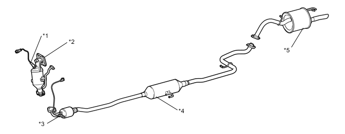
| *1 | Heated Oxygen Sensor | *2 | Exhaust Manifold (TWC: Front Catalyst) |
| *3 | No. 2 Heated Oxygen Sensor | *4 | Front Exhaust Pipe Assembly (TWC: Rear Catalyst) |
| *5 | Tail Exhaust Pipe Assembly | - | - |
CAUTION / NOTICE / HINT
Tech Tips
Read freeze frame data using the GTS. Freeze frame data records the engine condition when malfunctions are detected. When troubleshooting, freeze frame data can help determine if the vehicle was moving or stationary, if the engine was warmed up or not, if the air fuel ratio was lean or rich, and other data from the time the malfunction occurred.
PROCEDURE
-
CHECK ANY OTHER DTCS OUTPUT (IN ADDITION TO DTC P0420)
-
Connect the GTS to the DLC3.
-
Turn the ignition switch to ON.
-
Turn the GTS on.
-
Enter the following menus: Powertrain / Engine and ECT / Trouble Codes.
-
Read DTCs.
Result Result Proceed To DTC P0420 is output A P0420 and other DTCs are output B Tech Tips
If any DTCs other than P0420 are output, troubleshoot those DTCs first.
B 
GO TO DTC CHART Click here
A 
-
-
PERFORM ACTIVE TEST USING GTS (CONTROL THE INJECTION VOLUME FOR A/F SENSOR)
-
Connect the GTS to the DLC3.
-
Start the engine.
-
Turn the GTS on.
-
Warm up the engine at an engine speed of 2500 rpm for approximately 3 minutes.
-
Enter the following menus: Powertrain / Engine and ECT / Active Test / Control the Injection Volume for A/F Sensor.
-
Perform the Active Test operation with the engine idling (press the -12.5 or 12.5 button to change the fuel injection volume).
-
Monitor the voltage output of the heated oxygen sensor and No. 2 heated oxygen sensor (O2S B1S1 and O2S B1S2) displayed on the GTS.
Tech Tips
-
The Control the Injection Volume for A/F Sensor operation lowers the fuel injection volume by 12.5% or increases the injection volume by 12.5%.
-
If the sensor output voltage does not change (almost no reaction) while performing the Active Test, the sensor may be malfunctioning.
Result The heated oxygen sensors reacts in accordance with increases and decreases of the fuel injection volume: 12.5% = Rich output Higher than 0.5 V -12.5% = Lean output Below 0.4 V 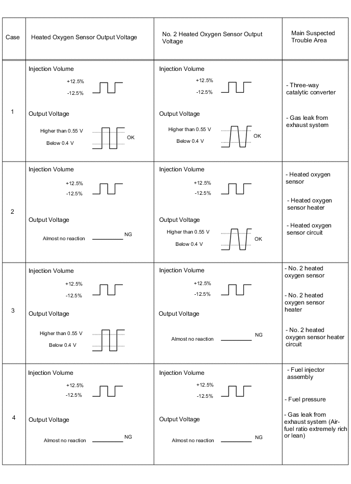
The following procedure enables the technician to check and graph the voltage output of both the heated oxygen sensors.
To display the graph, enter the following menus: Powertrain / Engine and ECT / Active Test / Control the Injection Volume for A/F Sensor / O2S B1S1 and O2S B1S2; then press the view button.
Result Result Proceed to Case 1 A Case 2 B Case 3 C Case 4 D -
B
REPLACE HEATED OXYGEN SENSOR Click here
C 
CHECK FOR EXHAUST GAS LEAK Click here
D
CHECK AND REPLACE EXTREMELY RICH OR LEAN ACTUAL AIR FUEL RATIO, AND GO TO STEP 3
A
-
-
CHECK FOR EXHAUST GAS LEAK
-
Check for exhaust gas leak.
OK No gas leak.
OK
REPLACE EXHAUST MANIFOLD (TWC: CATALYST) Click here
NG
CHECK FOR EXHAUST GAS LEAK POINT
-
-
CHECK FOR EXHAUST GAS LEAK
-
Check for exhaust gas leak.
OK No gas leak.
OK
REPLACE NO. 2 HEATED OXYGEN SENSOR Click here
NG
CHECK FOR EXHAUST GAS LEAK POINT
-