CAMSHAFT OIL CONTROL VALVE INSPECTION
PROCEDURE
-
INSPECT CAMSHAFT TIMING OIL CONTROL VALVE ASSEMBLY
-
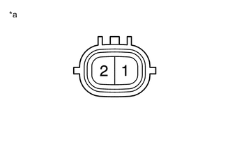
Text in Illustration *a Component without harness connected
(Camshaft Timing Oil Control Valve Assembly)
Measure the resistance according to the value(s) in the table below.
Standard Resistance Tester Connection Condition Specified Condition 1 - 2 20°C (68°F) 6.9 to 7.9 Ω If the result is not as specified, replace the camshaft timing oil control valve assembly.
-
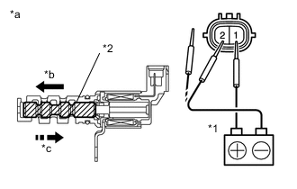
Text in Illustration *1 Battery *2 Spool Valve *a Component without harness connected
(Camshaft Timing Oil Control Valve Assembly)
*b When Applied *c When Cut Off Connect the positive (+) lead from a battery to terminal 1 and the negative (-) lead to terminal 2, and check the movement of the valve.
OK Tester Connection Condition Specified Condition 1 - 2 Battery positive (+) voltage is applied Valve moves in direction of left arrow shown in the illustration Battery positive (+) voltage is cut off Valve moves in direction of right arrow shown in the illustration If the result is not as specified, replace the camshaft timing oil control valve assembly.
Note
Accumulation of foreign matter can cause minor pressure leaks. Minor pressure leaks will cause the camshaft to advance or retard, and this will cause a DTC to be set.
-