SFI SYSTEM, Diagnostic DTC:P0138
| DTC Code | DTC Name |
|---|---|
| P0138 | Oxygen Sensor Circuit High Voltage (Bank 1 Sensor 2) |
DESCRIPTION
Refer to DTC P0137 Click here.
| DTC No. | DTC Detection Condition | Trouble Area |
|---|---|---|
| P0138 | All of the following conditions are met (3 trip detection logic):
|
|
Tech Tips
-
*1: Target lambda value of the ECM.
-
Target lambda value is 1.0: stoichiometric air fuel ratio
-
Target lambda value is more than 1.0: lean control performed
-
Target lambda value is less than 1.0: rich control performed
-
*2: Condensation may form in the exhaust pipes after the engine is started and before the exhaust system has warmed up. If condensation exists, the sensor element may be damaged if the No. 2 heated oxygen sensor heater is heated excessively.
Therefore, the ECM will restrict the output of the No. 2 heated oxygen sensor heater until it determines condensation is not forming in the exhaust pipes. Dew point judgment is when the ECM judges that condensation is no longer forming.
-
The normal output voltage from the No. 2 heated oxygen sensor is 0 to 1.0 V.
WIRING DIAGRAM
Refer to DTC P0130 Click here.
CONFIRMATION DRIVING PATTERN
CAUTION:
When performing the confirmation driving pattern, obey all speed limits and traffic laws.
DTC P0138 is detected when the vehicle is driven with a city driving pattern at an average vehicle speed of approximately 50 km/h (30 mph) for approximately 30 minutes.
CAUTION / NOTICE / HINT
Note
-
Perform idle learning after replacing the ECM Click here.
-
Inspect the fuses for circuits related to this system before performing the following inspection procedure.
Tech Tips
-
Inspect the No. 2 heated oxygen sensor output voltage:
Read the No. 2 heated oxygen sensor output voltage using the GTS.
-
Connect the GTS to the DLC3.
-
Start the engine.
-
Allow the engine to idle for 20 minutes or more.
-
Turn the GTS on.
-
Enter the following menus: Powertrain / Engine and ECT / Data List / O2S B1S2.
-
Read the output voltage of the No. 2 heated oxygen sensor.
Standard voltage No. 2 Heated Oxygen sensor output is below 1.0 V. -
Sensor 1 refers to the sensor closest to the engine assembly.
-
Sensor 2 refers to the sensor farthest away from the engine assembly.
-
Read freeze frame data using the GTS. Freeze frame data records the engine condition when malfunctions are detected. When troubleshooting, freeze frame data can help determine if the vehicle was moving or stationary, if the engine was warmed up or not, if the air fuel ratio was lean or rich, and other data from the time the malfunction occurred.
PROCEDURE
-
INSPECT NO. 2 HEATED OXYGEN SENSOR
-
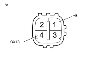
Text in Illustration *a Component without harness connected
(No. 2 Heated Oxygen Sensor)
Disconnect the No. 2 heated oxygen sensor connector.
-
Measure the resistance according to the value(s) in the table below.
Standard Resistance Tester Connection Condition Specified Condition 1 (+B) - 4 (OX1B) Always 10 kΩ or higher
NG 
REPLACE NO. 2 HEATED OXYGEN SENSOR Click here
OK 
-
-
CHECK HARNESS AND CONNECTOR (NO. 2 HEATED OXYGEN SENSOR - ECM)
-
Disconnect the B83 No.2 heated oxygen sensor connector.
-
Disconnect the B97 ECM connector (for LHD).
-
Disconnect the B101 ECM connector (for RHD).
-
Measure the resistance according to the value(s) in the table below.
Standard Resistance for LHD Tester Connection Condition Specified Condition B97-103 (OX1B) - B97-25 (HT1B) Always 10 kΩ or higher for RHD Tester Connection Condition Specified Condition B101-103 (OX1B) - B101-25 (HT1B) Always 10 kΩ or higher
OK
REPLACE ECM Click here
NG
REPAIR OR REPLACE HARNESS OR CONNECTOR
-