SFI SYSTEM, Diagnostic DTC:P0135
| DTC Code | DTC Name |
|---|---|
| P0135 | Oxygen Sensor Heater Circuit (Bank 1 Sensor 1) |
DESCRIPTION
Refer to DTC P0130 Click here.
Tech Tips
The ECM provides a pulse width modulated control circuit to adjust the current through the heater. The heated oxygen sensor heater circuit uses a relay on the +B side of the circuit.
| DTC No. | DTC Detection Condition | Trouble Area |
|---|---|---|
| P0135 | Open or short of heated oxygen sensor heater or related circuit (3 trip detection logic). |
|
Tech Tips
-
DTC P0135 is detected when the engine idles for 20 minutes.
WIRING DIAGRAM
Refer to DTC P0130 Click here.
CAUTION / NOTICE / HINT
Note
-
Perform idle learning after replacing the ECM Click here.
-
Inspect the fuses for circuits related to this system before performing the following inspection procedure.
Tech Tips
-
Sensor 1 refers to the sensor closest to the engine assembly.
-
Sensor 2 refers to the sensor farthest away from the engine assembly.
-
Read freeze frame data using the GTS. Freeze frame data records the engine condition when malfunctions are detected. When troubleshooting, freeze frame data can help determine if the vehicle was moving or stationary, if the engine was warmed up or not, if the air fuel ratio was lean or rich, and other data from the time the malfunction occurred.
PROCEDURE
-
INSPECT HEATED OXYGEN SENSOR (HEATER RESISTANCE)
-
Inspect the heated oxygen sensor Click here.
NG 
REPLACE HEATED OXYGEN SENSOR Click here
OK 
-
-
CHECK TERMINAL VOLTAGE (HEATED OXYGEN SENSOR)
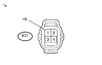
Text in Illustration *a Front view of wire harness connector
(to Heated Oxygen Sensor)
-
Disconnect the B37 heated oxygen sensor connector.
-
Turn the ignition switch to ON
-
Measure the voltage according to the value(s) in the table below.
Standard Voltage Tester Connection Switch Condition Specified Condition B37-1 (+B) - Body ground Ignition switch ON 11 to 14 V
NG 
INSPECT NO.1 INTEGRATION RELAY (EFI MAIN RELAY) Click here
OK
-
-
CHECK HARNESS AND CONNECTOR (HEATED OXYGEN SENSOR - ECM)
-
Disconnect the B37 heated oxygen sensor connector.
-
Disconnect the B97 ECM connector (for LHD).
-
Disconnect the B101 ECM connector (for RHD).
-
Measure the resistance according to the value(s) in the table below.
Standard Resistance for LHD Tester Connection Condition Specified Condition B37-2 (HT1A) - B97-24 (HT1A) Always Below 1 Ω B37-2 (HT1A) or B97-24 (HT1A) - Body ground Always 10 kΩ or higher for RHD Tester Connection Condition Specified Condition B37-2 (HT1A) - B101-24 (HT1A) Always Below 1 Ω B37-2 (HT1A) or B101-24 (HT1A) - Body ground Always 10 kΩ or higher
NG
REPAIR OR REPLACE HARNESS OR CONNECTOR
OK
-
-
CHECK WHETHER DTC OUTPUT RECURS
-
Connect the GTS to the DLC3.
-
Turn the ignition switch to ON.
-
Turn the GTS on.
-
Clear DTCs Click here.
-
Turn the ignition switch off and wait for at least 30 seconds.
-
Turn the ignition switch to ON.
-
Turn the GTS on.
-
Start the engine.
-
Allow the engine to idle for 20 minutes or more.
-
Enter the following menus: Powertrain / Engine and ECT / Trouble Codes.
-
Read the pending DTCs.
Result Result Proceed to DTC is not output A DTC P0135 is output B
A
CHECK FOR INTERMITTENT PROBLEMS Click here
B
REPLACE ECM Click here
-
-
INSPECT NO.1 INTEGRATION RELAY (EFI MAIN RELAY)
-
Inspect the No. 1 integration relay Click here.
NG
REPLACE NO.1 INTEGRATION RELAY Click here
OK
-
-
CHECK HARNESS AND CONNECTOR (NO. 1 INTEGRATION RELAY - HEATED OXYGEN SENSOR)
-
Remove the No. 1 integration relay from the engine room relay block.
-
Disconnect the B37 heated oxygen sensor connector.
-
Measure the resistance according to the value(s) in the table below.
Standard Resistance Tester Connection Condition Specified Condition 1E-4 - B37-1 (+B) Always Below 1 Ω 1E-4 or B37-1 (+B) - Body ground Always 10 kΩ or higher
OK
CHECK ECM POWER SOURCE CIRCUIT Click here
NG
REPAIR OR REPLACE HARNESS OR CONNECTOR
-