SFI SYSTEM, Diagnostic DTC:P0117, P0118
| DTC Code | DTC Name |
|---|---|
| P0117 | Engine Coolant Temperature Circuit Low Input |
| P0118 | Engine Coolant Temperature Circuit High Input |
DESCRIPTION
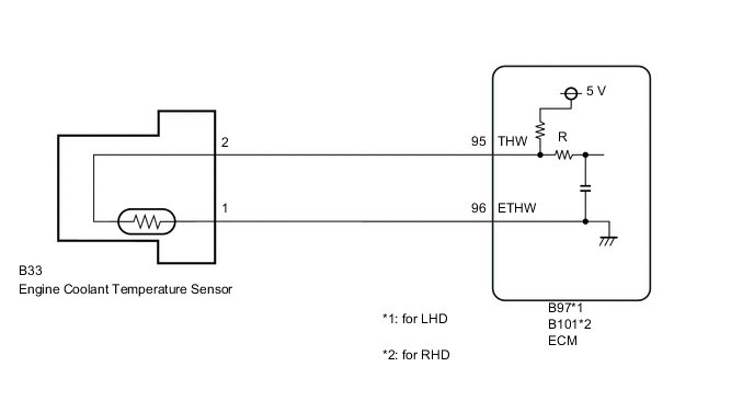
A thermistor is built into the engine coolant temperature sensor and changes its resistance value according to the engine coolant temperature. The structure of the sensor and connection to the ECM are the same as that of the intake air temperature sensor.
Tech Tips
-
When the engine coolant temperature sensor output is outside the normal range, the ECM interprets this as a malfunction.
-
If DTC P0117 or P0118 is detected, the ECM performs engine control using an estimated engine coolant temperature calculated from the intake air temperature at the time of engine start and the intake air volume.
| DTC No. | DTC Detection Condition | Trouble Area |
|---|---|---|
| P0117 | Engine coolant temperature sensor output is 0.05 V or less for 0.5 seconds (3 trip detection logic). |
|
| P0118 | Engine coolant temperature sensor output is 4.95 V or higher for 0.5 seconds (3 trip detection logic). |
|
Tech Tips
-
DTC P0117 and P0118 are detected when the engine idles for approximately 10 minutes.
-
When any of these DTCs are output, check the engine coolant temperature using the GTS. Enter the following menus: Powertrain / Engine and ECT / Data List / Coolant Temp.
| Temperature Displayed | Malfunction |
|---|---|
| -40°C (-40°F) | Open circuit |
| 140°C (284°F) or higher | Short circuit |
WIRING DIAGRAM
CAUTION / NOTICE / HINT
Note
Perform idle learning after replacing the ECM Click here.
Tech Tips
Read freeze frame data using the GTS. Freeze frame data records the engine condition when malfunctions are detected. When troubleshooting, freeze frame data can help determine if the vehicle was moving or stationary, if the engine was warmed up or not, if the air fuel ratio was lean or rich, and other data from the time the malfunction occurred.
PROCEDURE
-
READ VALUE USING GTS (COOLANT TEMP)
-
Connect the GTS to the DLC3.
-
Turn the ignition to ON.
-
Turn the GTS on.
-
Enter the following menus: Powertrain / Engine and ECT / Data List / Coolant Temp.
-
Read the value displayed on the GTS.
Standard value Between 75°C and 100°C (167°F and 212°F) with warm engine. Result Result Proceed to -40°C (-40°F) A 140°C (284°F) or higher B Between 75 and 100°C (167 and 212°F) C Tech Tips
-
If there is an open circuit, the GTS indicates -40°C (-40°F).
-
If there is a short circuit, the GTS indicates 140°C (284°F) or higher.
-
B 
READ VALUE USING GTS (CHECK FOR SHORT IN WIRE HARNESS) Click here
C 
CHECK FOR INTERMITTENT PROBLEMS Click here
A 
-
-
READ VALUE USING GTS (CHECK FOR OPEN IN WIRE HARNESS)
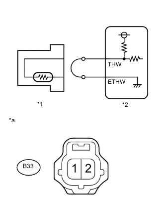
Text in Illustration *1 Engine Coolant Temperature Sensor *2 ECM *a Front view of wire harness connector
(to Engine Coolant Temperature Sensor)
-
Disconnect the engine coolant temperature sensor connector.
-
Connect terminals 2 and 1 of the engine coolant temperature sensor wire harness side connector.
-
Connect the GTS to the DLC3.
-
Turn the ignition switch to ON.
-
Turn the GTS on.
-
Enter the following menus: Powertrain / Engine and ECT / Data List / Coolant Temp.
-
Read the value displayed on the GTS.
Standard value 140°C (284°F) or higher
OK
REPLACE ENGINE COOLANT TEMPERATURE SENSOR Click here
NG
-
-
CHECK HARNESS AND CONNECTOR (ENGINE COOLANT TEMPERATURE SENSOR - ECM)
-
Disconnect the B33 engine coolant temperature sensor connector.
-
Disconnect the B97 ECM connector (for LHD).
-
Disconnect the B101 ECM connector (for RHD).
-
Measure the resistance according to the value(s) in the table below.
Standard Resistance for LHD Tester Connection Condition Specified Condition B33-2 - B97-95 (THW) Always Below 1 Ω B33-1 - B97-96 (ETHW) Always Below 1 Ω for RHD Tester Connection Condition Specified Condition B33-2 - B101-95 (THW) Always Below 1 Ω B33-1 - B101-96 (ETHW) Always Below 1 Ω
OK
REPLACE ECM Click here
NG
REPAIR OR REPLACE HARNESS OR CONNECTOR
-
-
READ VALUE USING GTS (CHECK FOR SHORT IN WIRE HARNESS)
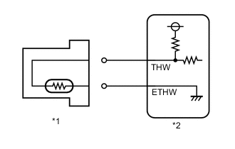
Text in Illustration *1 Engine Coolant Temperature Sensor *2 ECM
-
Disconnect the B33 engine coolant temperature sensor connector.
-
Connect the GTS to the DLC3.
-
Turn the ignition switch to ON.
-
Turn the GTS on.
-
Enter the following menus: Powertrain / Engine and ECT / Data List / Coolant Temp.
-
Read the value displayed on the GTS.
Standard value -40°C (-40°F)
OK
REPLACE ENGINE COOLANT TEMPERATURE SENSOR Click here
NG
-
-
CHECK HARNESS AND CONNECTOR (ENGINE COOLANT TEMPERATURE SENSOR - ECM)
-
Disconnect the B33 engine coolant temperature sensor connector.
-
Disconnect the B97 ECM connector (for LHD).
-
Disconnect the B101 ECM connector (for RHD).
-
Measure the resistance according to the value(s) in the table below.
Standard Resistance for LHD Tester Connection Condition Specified Condition B33-2 or B97-95 (THW) - Body ground Always 10 kΩ or higher for RHD Tester Connection Condition Specified Condition B33-2 or B101-95 (THW) - Body ground Always 10 kΩ or higher
OK
REPLACE ECM Click here
NG
REPAIR OR REPLACE HARNESS OR CONNECTOR
-