SFI SYSTEM, Diagnostic DTC:P0107, P0108
| DTC Code | DTC Name |
|---|---|
| P0107 | Manifold Absolute Pressure / Barometric Pressure Circuit Low Input |
| P0108 | Manifold Absolute Pressure / Barometric Pressure Circuit High Input |
DESCRIPTION
Refer to DTC P0106 Click here.
| DTC No. | DTC Detecting Condition | Trouble Area |
|---|---|---|
| P0107 | The output voltage from the vacuum sensor remains 0.43 V or less for 2 seconds or more (3 trip detection logic). |
|
| P0108 | The output voltage from the vacuum sensor remains 4.84 V or higher for 2 seconds or more (3 trip detection logic). |
|
Note
If any DTCs related to the manifold absolute pressure sensor, accelerator pedal sensor assembly and camshaft position sensor are output simultaneously, inspect the VC circuit of each component.
Tech Tips
-
DTC P0107 and P0108 are detected when the engine idling for approximately 15 seconds.
-
When any of these DTCs is output, check the manifold absolute pressure using the GTS. Enter the following menus: Powertrain / Engine and ECT / Data List / MAP.
| Manifold Absolute Pressure | Malfunction |
|---|---|
| Approximately 0 kPa (0 mmHg) |
|
| 140 kPa (1050 mmHg) or more |
|
WIRING DIAGRAM
Refer to DTC P0106 Click here.
CAUTION / NOTICE / HINT
Note
Perform idle learning after replacing the ECM Click here.
Tech Tips
Read freeze frame data using the GTS. Freeze frame data records the engine condition when malfunctions are detected. When troubleshooting, freeze frame data can help determine if the vehicle was moving or stationary, if the engine was warmed up or not, if the air fuel ratio was lean or rich, and other data from the time the malfunction occurred.
PROCEDURE
-
READ VALUE USING GTS (MAP)
-
Connect the GTS to the DLC3.
-
Turn the ignition switch to ON.
-
Turn the GTS on.
-
Enter the following menus: Powertrain / Engine and ECT / Data List / MAP.
-
Read the MAP value.
Standard value Switch Condition Tester Display Ignition switch ON 80 to 110 kPa (600 to 825 mmHg) Tech Tips
Standard atmospheric pressure is 101 kPa (758 mmHg). For every 100 m (328 ft.) increase in elevation, pressure drops by 1 kPa (7.50 mmHg). This varies by weather (high atmospheric pressure, low atmospheric pressure).
OK 
CHECK FOR INTERMITTENT PROBLEMS Click here
NG 
-
-
CHECK TERMINAL VOLTAGE (MANIFOLD ABSOLUTE PRESSURE SENSOR)
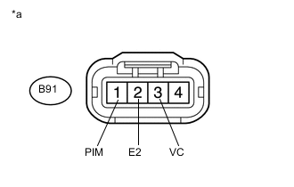
Text in Illustration *a Front view of wire harness connector
(to Manifold Absolute Pressure Sensor)
-
Disconnect the B91 manifold absolute pressure sensor connector.
-
Turn the ignition switch to ON.
-
Measure the voltage according to the value(s) in the table below.
Standard Voltage Tester Connection Switch Condition Specified Condition B91-3 (VC) - B91-2 (E2) Ignition switch ON 4.5 to 5.5 V B91-1 (PIM) - B91-2 (E2) Ignition switch ON 4.5 to 5.5 V
NG 
CHECK HARNESS AND CONNECTOR (MANIFOLD ABSOLUTE PRESSURE SENSOR - ECM) Click here
OK
-
-
REPLACE MANIFOLD ABSOLUTE PRESSURE SENSOR
-
Replace the manifold absolute pressure sensor Click here.
NEXT
-
-
CHECK WHETHER DTC OUTPUT RECURS (DTC P0107 OR P0108)
-
Connect the GTS to the DLC3.
-
Turn the ignition switch to ON.
-
Turn the GTS on.
-
Clear DTCs Click here.
-
Turn the ignition switch off and wait for at least 30 seconds.
-
Turn the ignition switch to ON.
-
Turn the GTS on.
-
Start the engine.
-
Allow the engine to idle for 15 seconds or more.
-
Enter the following menus: Powertrain / Engine and ECT / Trouble Codes.
-
Read the DTCs.
OK DTC is not output.
OK
END
NG
REPLACE ECM Click here
-
-
CHECK HARNESS AND CONNECTOR (MANIFOLD ABSOLUTE PRESSURE SENSOR - ECM)
-
Disconnect the B91 manifold absolute pressure sensor connector.
-
Disconnect the B97 ECM connector (for LHD).
-
Disconnect the B101 ECM connector (for RHD).
-
Measure the resistance according to the value(s) in the table below.
Standard Resistance for LHD Tester Connection Condition Specified Condition B91-3 (VC) - B97-118 (VC2) Always Below 1 Ω B91-1 (PIM) - B97-87 (PIM) Always Below 1 Ω B91-2 (E2) - B97-85 (E21) Always Below 1 Ω B91-3 (VC) or B97-118 (VC2) - Body ground Always 10 kΩ or higher B91-1 (PIM) or B97-87 (PIM) - Body ground Always 10 kΩ or higher for RHD Tester Connection Condition Specified Condition B91-3 (VC) - B101-118 (VC2) Always Below 1 Ω B91-1 (PIM) - B101-87 (PIM) Always Below 1 Ω B91-2 (E2) - B101-85 (E21) Always Below 1 Ω B91-3 (VC) or B101-118 (VC2) - Body ground Always 10 kΩ or higher B91-1 (PIM) or B101-87 (PIM) - Body ground Always 10 kΩ or higher
OK
REPLACE ECM Click here
NG
REPAIR OR REPLACE HARNESS OR CONNECTOR
-