SFI SYSTEM, Diagnostic DTC:P0704
| DTC Code | DTC Name |
|---|---|
| P0704 | Clutch Switch Input Circuit Malfunction |
DESCRIPTION
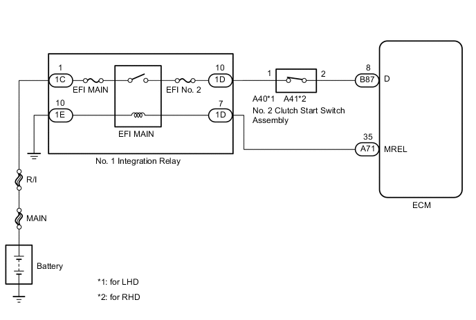
The No. 2 clutch start switch assembly is mounted on the clutch pedal. The switch is turned off when depressing the clutch pedal, and transmits a signal to the ECM.
| DTC No. | DTC Detection Condition | Trouble Area |
|---|---|---|
| P0704 | No clutch switch signals to ECM despite gears being shifted (3 trip detection logic) |
|
Tech Tips
DTC P0704 is stored when the gears are shifted more than 20 times.
WIRING DIAGRAM
CAUTION / NOTICE / HINT
Note
-
Perform electronic throttle learning after replacing the ECM Click here.
-
Inspect the fuses for circuits related to this system before performing the following inspection procedure.
PROCEDURE
-
CHECK SWITCH INSTALLATION (NO. 2 CLUTCH START SWITCH ASSEMBLY)
-
Check the No. 2 clutch start switch assembly installation Click here.
OK The switch is installed correctly.
NG 
SECURELY REINSTALL (NO. 2 CLUTCH START SWITCH ASSEMBLY) Click here
OK 
-
-
INSPECT NO. 2 CLUTCH START SWITCH ASSEMBLY
-
Inspect the No. 2 Clutch Start Switch Assembly Click here.
NG
REPLACE NO. 2 CLUTCH START SWITCH ASSEMBLY Click here
OK
-
-
CHECK TERMINAL VOLTAGE (NO. 2 CLUTCH START SWITCH ASSEMBLY)
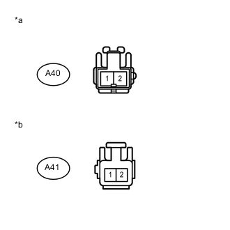
Text in Illustration *a Front view of wire harness connector
(to No. 2 Clutch Start Switch Assembly for LHD)
*b Front view of wire harness connector
(to No. 2 Clutch Start Switch Assembly for RHD)
-
Disconnect the No. 2 Clutch Start Switch Assembly connector.
-
Turn the ignition switch to ON.
-
Measure the voltage according to the value(s) in the table below.
Standard Voltage for LHD Tester Connection Switch Condition Specified Condition A40-1 - Body ground Ignition switch ON 11 to 14 V for RHD Tester Connection Switch Condition Specified Condition A41-1 - Body ground Ignition switch ON 11 to 14 V
NG 
CHECK HARNESS AND CONNECTOR (NO. 2 CLUTCH START SWITCH ASSEMBLY - NO. 1 INTEGRATION RELAY) Click here
OK
-
-
CHECK HARNESS AND CONNECTOR (ECM - NO. 2 CLUTCH START SWITCH ASSEMBLY)
-
Disconnect the ECM connector.
-
Disconnect the No. 2 clutch start switch assembly connector.
-
Measure the resistance according to the value(s) in the table below.
Standard Resistance for LHD Tester Connection Condition Specified Condition B87-8 (D) - A40-2 Always Below 1 Ω B87-8 (D) or A40-2 - Body ground Always 10 kΩ or higher for RHD Tester Connection Condition Specified Condition B87-8 (D) - A41-2 Always Below 1 Ω B87-8 (D) or A41-2 - Body ground Always 10 kΩ or higher
OK
REPLACE ECM Click here
NG
REPAIR OR REPLACE HARNESS OR CONNECTOR
-
-
CHECK HARNESS AND CONNECTOR (NO. 2 CLUTCH START SWITCH ASSEMBLY - NO. 1 INTEGRATION RELAY)
-
Disconnect the No. 2 clutch start switch assembly connector.
-
Remove the No. 1 integration relay from the engine room relay block.
-
Measure the resistance according to the value(s) in the table below.
Standard Resistance for LHD Tester Connection Condition Specified Condition A40-1 - 1D-10 Always Below 1 Ω A40-1 or 1D-10 - Body ground Always 10 kΩ or higher for RHD Tester Connection Condition Specified Condition A41-1 - 1D-10 Always Below 1 Ω A41-1 or 1D-10 - Body ground Always 10 kΩ or higher
OK
CHECK ECM POWER SOURCE CIRCUIT Click here
NG
REPAIR OR REPLACE HARNESS OR CONNECTOR
-