SFI SYSTEM TERMINALS OF ECM
Tech Tips
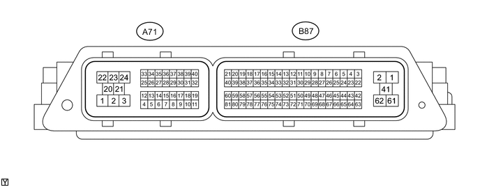
The standard normal voltage between each pair of ECM terminals is shown in the table below. The appropriate conditions for checking each pair of terminals are also indicated. The result of checks should be compared with the standard normal voltage for that pair of terminals, and displayed in the "Specified Condition" column. The illustration above can be used as a reference to identify the ECM terminal locations.
| Terminal No. (Symbol) | Wiring Color | Terminal Description | Condition | Specified Condition |
|---|---|---|---|---|
| A71-22 (BATT) - A71-1 (E1) | V - W-B | Battery (for measuring battery voltage and for ECM memory) | Always | 11 to 14 V |
| A71-4 (IGSW) - A71-1 (E1) | R - W-B | Ignition switch | Ignition switch ON | 11 to 14 V |
| A71-24 (+B) - A71-1 (E1) | B - W-B | Power source of ECM | Ignition switch ON | 11 to 14 V |
| A71-23 (+B2) - A71-1 (E1) | B - W-B | Power source of ECM | Ignition switch ON | 11 to 14 V |
| A71-35 (MREL) - A71-1 (E1) | GR - W-B | EFI MAIN relay | Ignition switch ON | 11 to 14 V |
| B87-55 (VCTA) - B87-35 (ETA) | L - R | Power source of throttle position sensor (specific voltage) | Ignition switch ON | 4.5 to 5.5 V |
| A71-11 (VCPA) - A71-10 (EPA) | G - G | Power source of accelerator pedal position sensor (for VPA) | Ignition switch ON | 4.5 to 5.5 V |
| A71-19 (VCP2) - A71-18 (EPA2) | W - B | Power source of accelerator pedal position sensor (for VPA2) | Ignition switch ON | 4.5 to 5.5 V |
| B87-54 (VCPM) - B87-51 (EPIM) | V - G | Power source of manifold absolute pressure sensor (specific voltage) | Ignition switch ON | 4.5 to 5.5 V |
| B87-80 (VC) - A71-1 (E1) | LG - W-B | Power source of camshaft position sensor (specific voltage) | Ignition switch ON | 4.5 to 5.5 V |
| B87-50 (PIM) - B87-51 (EPIM) | B - G | Manifold absolute pressure sensor | Idling | 1.2 to 2.0 V |
| B87-14 (VTA1) - B87-35 (ETA) | Y - R | Throttle position sensor (for engine control) | Ignition switch ON, Accelerator pedal released | 0.2 to 1.0 V |
| Ignition switch ON, Accelerator pedal fully depressed | 4.2 to 4.6 V | |||
| B87-15 (VTA2) - B87-35 (ETA) | GR - R | Throttle position sensor (for sensor malfunction detection) | Ignition switch ON, Accelerator pedal released | 4.0 to 4.8 V |
| Ignition switch ON, Accelerator pedal fully depressed | 0.2 to 1.0 V | |||
| A71-9 (VPA) - A71-10 (EPA) | R - G | Accelerator pedal position sensor (for engine control) | Ignition switch ON, Accelerator pedal released | 0.7 to 1.2 V |
| Ignition switch ON, Accelerator pedal fully depressed | 2.8 to 4.6 V | |||
| A71-17 (VPA2) - A71-18 (EPA2) | L - B | Accelerator pedal position sensor (for sensor malfunction detection) | Ignition switch ON, Accelerator pedal released | 1.2 to 2.0 V |
| Ignition switch ON, Accelerator pedal fully depressed | 3.6 to 4.6 V | |||
| B87-13 (THA) - B87-51 (EPIM) | P - G | Intake air temperature sensor (built into manifold absolute pressure sensor) | Idling, Intake air temperature 20°C (68°F) | 1.5 to 3.0 V |
| B87-12 (THW) - B87-30 (ETHW) | R - P | Engine coolant temperature sensor | Idling, Engine coolant temperature 80°C (176°F) | 0.2 to 1.0 V |
| B87-45 (#10) - A71-21 (E01) B87-46 (#20) - A71-21 (E01) B87-67 (#30) - A71-21 (E01) |
R - W-B GR - W-B P - W-B |
Fuel injector assembly | Ignition switch ON | 11 to 14 V |
| B87-39 (IGT1) - A71-1 (E1) B87-40 (IGT2) - A71-1 (E1) B87-21 (IGT3) - A71-1 (E1) |
W - W-B BE - W-B G - W-B |
No. 1 ignition coil (ignition signal) | Idling | Pulse generation (See waveform 1) |
| B87-57 (G2+) - B87-58 (G2-) | R - W | Camshaft position sensor | Idling with warm engine | Pulse generation (See waveform 2) |
| B87-6 (NE+) - B87-5 (NE-) | Y - BR | Crankshaft position sensor | Idling with warm engine | Pulse generation (See waveform 2) |
| A71-40 (STA) - A71-1 (E1) | BR - W-B | Starter signal | Ignition switch ON | Below 1.5 V |
| Cranking | 5.5 V or more | |||
| A71-25 (NSW) - A71-1 (E1) | BE - W-B | Clutch start switch signal | Ignition switch ON (Clutch pedal fully depressed) |
Below 1.5 V |
| Ignition switch ON (Clutch pedal released) |
11 to 14 V | |||
| A71-26 (FC) - A71-1(E1) | V - W-B | Fuel pump control | Ignition switch ON | 11 to 14 V |
| Idling | Below 1.5 V | |||
| B87-34 (OX1A) - B87-32 (E2) | W - BR | Heated oxygen sensor | Engine speed maintained at 2500 rpm for 2 minutes after warming up sensor | Pulse generation (See waveform 3) |
| B87-36 (OX1B) - B87-37 (O1B-) | P - L | No. 2 heated oxygen sensor | Engine speed maintained at 2500 rpm for 2 minutes after warming up sensor | Pulse generation (See waveform 4) |
| B87-2 (HT1A) - A71-1 (E1) | G - W-B | Heated oxygen sensor heater | Ignition switch ON | 11 to 14 V |
| B87-41 (HT1B) - A71-1 (E1) | LG - W-B | No. 2 heated oxygen sensor | Ignition switch ON | 11 to 14 V |
| B87-17 (KNK1) - B87-18 (EKNK) | R - G | Knock sensor | Engine speed maintained at 4000 rpm after warming up engine | Pulse generation (See waveform 5) |
| B87-61 (OC1-) - B87-62 (OC1+) | R - W | Camshaft timing oil control valve assembly | Engine speed maintained at 2500 rpm after warming up engine | Pulse generation (See waveform 6) |
| B87-22 (EVP1) - A71-1 (E1) | L - W-B | Purge VSV | Ignition switch ON | 11 to 14 V |
| A71-31 (STP) - A71-1 (E1) | LG - W-B | Stop light switch assembly | Brake pedal depressed | 11 to 14 V |
| Brake pedal released | Below 1.5 V | |||
| A71-7 (ST1-) - A71-1 (E1) | Y- W-B | Stop light switch assembly | Brake pedal depressed | Below 1.5 V |
| Brake pedal released | 11 to 14 V | |||
| A71-5 (W) - A71-1 (E1) | B - W-B | MIL | Ignition switch ON (MIL goes on) | Below 3.0 V |
| A71-38 (SPD) - A71-1 (E1) | V - W-B | Speed signal from combination meter | Vehicle speed of approximately 20 km/h (12 mph) | Pulse generation (See waveform 7) |
| A71-2 (M+) - A71-3 (M-) | G - R | Throttle actuator | Idling with warm engine | Pulse generation (See waveform 8) |
| A71-16 (ELS2) - A71-1 (E1) | G - W-B | Electric load | Taillight switch on | 11 to 14 V |
| Taillight switch off | Below 1.5 V | |||
| A71-13 (TACH) - A71-1 (E1) | LG - W-B | Engine speed | Idling | Pulse generation (See waveform 11) |
| A71-30 (TC) - A71-1 (E1) | L - W-B | Terminal TC of DLC3 | Ignition switch ON | 11 to 14 V |
| B87-42 (EGR1) - A71-1 (E1) B87-64 (EGR2) - A71-1 (E1) B87-63 (EGR3) - A71-1 (E1) B87-43 (EGR4) - A71-1 (E1) |
R - W-B LG - W-B W - W-B Y - W-B |
EGR valve assembly | Engine racing | Pulse generation (See waveform 12) |
| B87-8 (D) - A71-1 (E1) | L - W-B | No. 2 clutch start switch assembly (upper) |
Ignition switch ON Clutch pedal released |
11 to 14 V |
| Ignition switch ON Clutch pedal depressed |
Below 1.5 V | |||
| B87-25 (R) - A71-1(E1) | R - W-B | Back-up light switch assembly signal | Back-up light switch on | 11 to 14 V |
| A71-34 (FANL) - A71-1 (E1) | R - W-B | FAN NO. 1 relay | Ignition switch ON Cooling fan not operated |
11 to 14 V |
| Idling with A/C on or High engine coolant temperature Cooling fan operated |
Below 1.5 V | |||
| A71-33 (FANH) - A71-1 (E1) | G - W-B | FAN NO. 2 relay | Idling with high engine coolant temperature Cooling fan operated at high speed |
Below 1.5 V |
| A71-28 (CANH) - A71-1 (E1) | L - W-B | CAN communication line | Ignition switch ON | Pulse generation (See waveform 9) |
| A71-36 (CANL) - A71-1 (E1) | W - W-B | CAN communication line | Ignition switch ON | Pulse generation (See waveform 10) |
| A71-29 (CANP)- A71-1 (E1) | B - W-B | CAN communication line | Ignition switch ON | Pulse generation (See waveform 9) |
| A71-37 (CANN)- A71-1 (E1) | W - W-B | CAN communication line | Ignition switch ON | Pulse generation (See waveform 10) |
| A71-15 (NEO)*1 - A71-1 (E1) | V - W-B | Crankshaft position sensor signal | Idling with warm engine | Pulse generation (See waveform 13) |
-
*1: w/ Entry and Start System
-
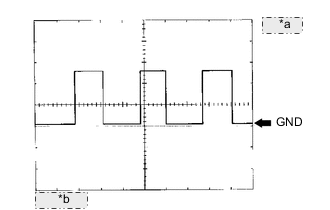
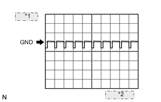
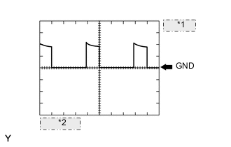
WAVEFORM 1
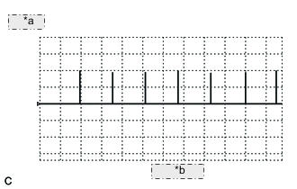
*a 2 V/DIV *b 100 ms/DIV Igniter IGT signal (from ECM to igniter) Terminal No. (Symbol) Tool Setting Condition B87-39 (IGT1) - A71-1 (E1) 2 V/DIV, 100 ms/DIV Idling B87-40 (IGT2) - A71-1 (E1) 2 V/DIV, 100 ms/DIV Idling B87-21 (IGT3) - A71-1 (E1) 2 V/DIV, 100 ms/DIV Idling Tech Tips
The wavelength becomes shorter as engine rpm increases.
-
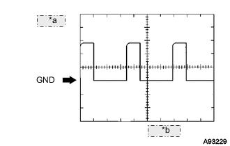
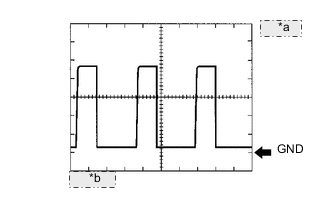
WAVEFORM 2
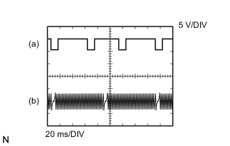
Camshaft position sensor and Crankshaft position sensor Terminal No. (Symbol) Tool Setting Condition (a) B87-57 (G2+) - B87-58 (G2-) 5 V/DIV, 20 ms/DIV Idling with warm engine (b) B87-6 (NE+) - B87-5 (NE-) 5 V/DIV, 20 ms/DIV Idling with warm engine Tech Tips
The wavelength becomes shorter as engine rpm increases.
-
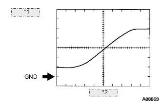
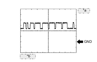
WAVEFORM 3
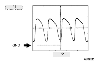
*1 200 mV/DIV *2 200 ms/DIV Heated oxygen sensor Terminal No. (Symbol) Tool Setting Condition B87-34 (OX1A) - B87-32 (E2) 200 mV/DIV, 200 ms/DIV Engine RPM maintained at 2500 rpm after engine warmed up Tech Tips
In the Data List, the item O2S B1S1 shows the ECM input values of the heated oxygen sensor.
-
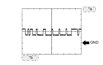
WAVEFORM 4
*1 200 mV/DIV *2 200 ms/DIV No. 2 heated oxygen sensor Terminal No. (Symbol) Tool Setting Condition B87-36 (OX1B) - B87-37 (O1B-) 200 mV/DIV, 200 ms/DIV Engine RPM maintained at 2500 rpm after engine warmed up Tech Tips
In the Data List, the item O2S B1S2 shows the ECM input values of the No. 2 heated oxygen sensor.
-
WAVEFORM 5
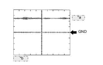
*a 1 V/DIV *b 1 ms/DIV Knock sensor Terminal No. (Symbol) Tool Setting Condition B87-17 (KNK1) - B87-18 (EKNK) 1 V/DIV, 1 ms/DIV Engine RPM maintained at 4000 rpm after engine warmed up Tech Tips
-
The wavelength becomes shorter as engine rpm increases.
-
The waveforms and amplitudes displayed differ slightly depending on the vehicle condition.
-
-
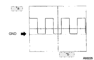
WAVEFORM 6
*a 5 V/DIV *b 1 ms/DIV Camshaft Timing Oil Control Valve Terminal No. (Symbol) Tool Setting Condition B87-61 (OC1-) - B87-62 (OC1+) 5 V/DIV, 1 ms/DIV Engine RPM maintained at 2500 rpm after warming up engine -
WAVEFORM 7
*a 5 V/DIV *b 20 ms/DIV Vehicle Speed Signal Terminal No. (Symbol) Tool Setting Condition A71-38 (SPD) - A71-1 (E1) 5 V/DIV, 20 ms/DIV Vehicle speed of approximately 20 km/h (12 mph) Tech Tips
The wavelength becomes shorter as the vehicle speed increases.
-
WAVEFORM 8
*1 20 V/DIV *2 500 μs/DIV Throttle actuator Terminal No. (Symbol) Tool Setting Condition A71-2 (M+) - A71-3 (M-) 20 V/DIV, 500 μs/DIV Idling with warm engine Tech Tips
The duty ratio varies depending on the throttle actuator operation.
-
WAVEFORM 9
*a 1 V/DIV *b 10 μs/DIV CAN Communication signal (Reference) Terminal No. (Symbol) Tool Setting Condition A71-28 (CANH) - A71-1 (E1) 1 V/DIV, 10 μs/DIV Ignition switch ON A71-29 (CANP) - A71-1 (E1) 1 V/DIV, 10 μs/DIV Ignition switch ON Tech Tips
The waveform varies depending on the CAN communication signal.
-
WAVEFORM 10
*a 1 V/DIV *b 10 μs/DIV CAN Communication signal (Reference) Terminal No. (Symbol) Tool Setting Condition A71-36 (CANL) - A71-1 (E1) 1 V/DIV, 10 μ/DIV Ignition switch ON A71-37 (CANN)- A71-1 (E1) 1 V/DIV, 10 μs/DIV Ignition switch ON Tech Tips
The waveform varies depending on the CAN communication signal.
-
WAVEFORM 11
*a 5 V/DIV *b 10 ms/DIV Engine speed signal Terminal No. (Symbol) Tool Setting Condition A71-13 (TACH) - A71-1 (E1) 5 V/DIV, 10 ms/DIV Idling Tech Tips
The wavelength becomes shorter as engine rpm increases.
-
WAVEFORM 12
*1 10 V/DIV *2 500 μs/DIV EGR valve assembly Terminal No. (Symbol) Tool Setting Condition B87-42 (EGR1) - A71-1 (E1) 10 V/DIV, 500 μs/DIV Engine racing B87-64 (EGR2) - A71-1 (E1) 10 V/DIV, 500 μs/DIV Engine racing B87-63 (EGR3) - A71-1 (E1) 10 V/DIV, 500 μs/DIV Engine racing B87-43 (EGR4) - A71-1 (E1) 10 V/DIV, 500 μs/DIV Engine racing -
WAVEFORM 13
*a 1 V/DIV *b 2 ms/DIV Crankshaft Position Sensor Signal Terminal No. (Symbol) Tool Setting Condition A71-15 (NEO) - A71-1 (E1) 1 V/DIV, 2 ms/DIV Idling with warm engine Tech Tips
The wavelength becomes shorter as engine rpm increases.