REAR BUMPER REASSEMBLY
PROCEDURE
-
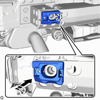
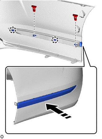
INSTALL REAR BUMPER SIDE SUPPORT LH
-
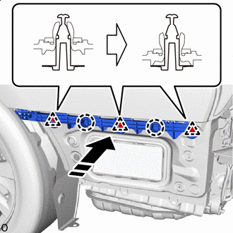

Install in this Direction Attach the claw as shown in the illustration.
-
Attach the clip to install the rear bumper side support LH as shown in the illustration.
-
-
INSTALL REAR BUMPER SIDE SUPPORT RH
Tech Tips
Use the same procedure described for the LH side.
-
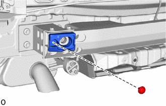
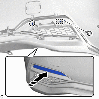
INSTALL REAR BUMPER LOWER SIDE RETAINER LH
-
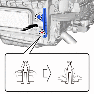
Install in this Direction Attach the claw as shown in the illustration.
-
Attach the clip to install the rear bumper lower side retainer LH as shown in the illustration.
-
-
INSTALL REAR BUMPER LOWER SIDE RETAINER RH
Tech Tips
Use the same procedure described for the LH side.
-
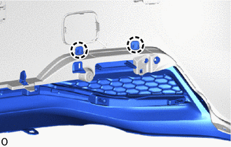
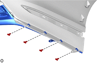
INSTALL REAR BUMPER LOWER RETAINER LH
-
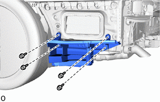
Install the rear bumper lower retainer LH with the 4 screws.
-
-
INSTALL REAR BUMPER LOWER RETAINER RH
Tech Tips
Use the same procedure described for the LH side.
-
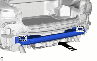
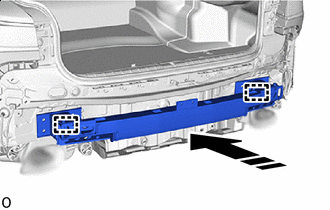
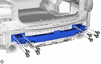
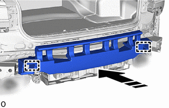
INSTALL REAR BUMPER REINFORCEMENT SUB-ASSEMBLY
-
for Type A:
-
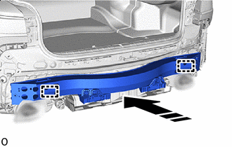
Install in this Direction Insert the guide.
-
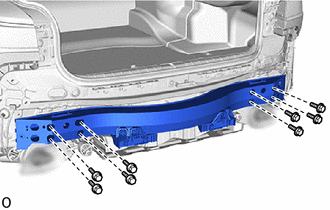
Install the rear bumper reinforcement sub-assembly with the 8 bolts.
- Torque:
- 20 N*m { 204 kgf*cm, 15 ft.*lbf }
-
-
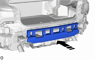
for Type B:
-
Install in this Direction Insert the guide.
-
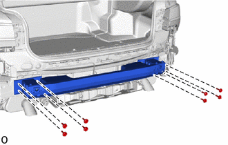
Install the rear bumper reinforcement sub-assembly with the 8 bolts.
- Torque:
- 20 N*m { 204 kgf*cm, 15 ft.*lbf }
-
-
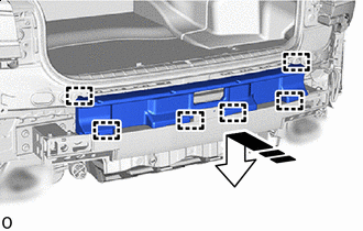
for Type C:
-
Install in this Direction Insert the guide.
-
Install the rear bumper reinforcement sub-assembly with the 8 bolts.
- Torque:
- 20 N*m { 204 kgf*cm, 15 ft.*lbf }
-
-
-
INSTALL REAR BUMPER ARM REINFORCEMENT LH
-
for Type A:
-
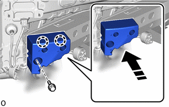
Install in this Direction Attach the claw.
-
Install the rear bumper arm reinforcement LH with the bolt.
-
-
for Type B:
-
Install in this Direction Attach the claw.
-
Install the rear bumper arm reinforcement LH with the clip.
-
-
-
INSTALL REAR BUMPER ARM REINFORCEMENT RH
Tech Tips
Use the same procedure described for the LH side.
-
INSTALL REAR BUMPER ENERGY ABSORBER
-
for Type A:
-
Install in this Direction Attach the guide to install the rear bumper energy absorber.
-
-
for Type B:
-
Install in this Direction Install the rear bumper energy absorber.
-
-
for Type C:
-
Install in this Direction Attach the guide to install the rear bumper energy absorber.
-
-
-
INSTALL REAR BUMPER ARM
Tech Tips
When installing the rear bumper arm, heat the rear bumper cover using a heat light.
Standard Item Temperature Rear Bumper Cover 20 to 30°C (68 to 86°F) Note
Do not heat the rear bumper cover excessively.
-
When reusing the rear bumper cover:
-
Using a heat light, heat the rear bumper cover installation surface.
-
Remove the double-sided tape from the rear bumper cover.
-
Wipe off any tape adhesive residue with cleaner.
-
-
Using a heat light, heat the rear bumper cover.
-
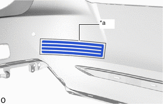
Remove the peeling paper from a new 2 rear bumper arms.
-
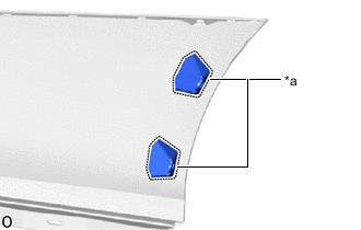
*a Mark-off Line Align the 2 rear bumper arms with the mark-off line of the rear bumper cover.
Tech Tips
-
Press the rear bumper arm firmly to install it.
-
Use the same procedure for the RH and LH side.
-
-
-
INSTALL NO. 1 MOULDING TAPE
Tech Tips
When installing the No. 1 moulding tape, heat the rear bumper cover using a heat light.
Standard Item Temperature Rear Bumper Cover 20 to 30°C (68 to 86°F) Note
Do not heat the rear bumper cover excessively.
-
When reusing the rear bumper cover:
-
Using a heat light, heat the rear bumper cover installation surface.
-
Remove the double-sided tape from the rear bumper cover.
-
Wipe off any tape adhesive residue with cleaner.
-
-
Using a heat light, heat the rear bumper cover.
-
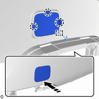
Remove the peeling paper from a new No. 1 moulding tape.
-
*a Mark-off Line Align the No. 1 moulding tape with the mark-off line of the rear bumper cover.
Tech Tips
-
Press the No. 1 moulding tape firmly to install it.
-
Use the same procedure for the RH and LH side.
-
-
Remove the application tape.
-
-
INSTALL REAR BUMPER PIECE LH
-
Install in this Direction Install the anti-drop hook.
-
Attach the claw to install the rear bumper piece LH.
-
-
INSTALL REAR BUMPER PIECE RH
Tech Tips
Use the same procedure described for the LH side.
-
INSTALL REAR BUMPER CENTER MOULDING
-
Attach the guide and claw to install the rear bumper center moulding as shown in the illustration.
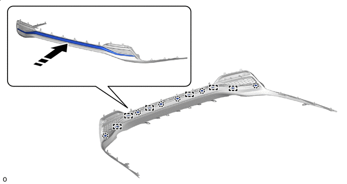
Install in this Direction - - -
Install the 6 screws.
-
-
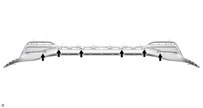
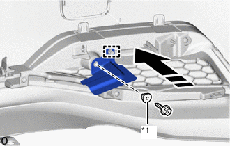
INSTALL REAR BUMPER LOWER COVER
-
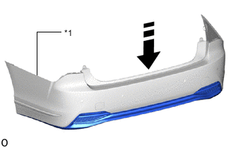
*1 Rear Bumper Cover Install in this Direction Insert the rear bumper cover.
-
Attach the claw.
Tech Tips
Use the same procedure for the RH and LH side.
-
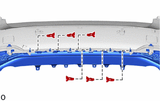
Install the 6 clips as shown in the illustration.
-
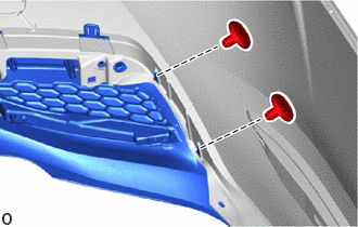
Install the 2 clips.
Tech Tips
Use the same procedure for the RH and LH side.
-
Install the 4 clips as shown in the illustration.
Tech Tips
Use the same procedure for the RH and LH side.
-
-
INSTALL REFLEX REFLECTOR ASSEMBLY LH
-
Install in this Direction Attach the guide and claw to install the reflex reflector assembly LH as shown in the illustration.
-
Install the screw.
-
-
INSTALL REFLEX REFLECTOR ASSEMBLY RH
Tech Tips
Use the same procedure described for the LH side.
-
INSTALL REAR BUMPER SIDE MOULDING LH
-
Install in this Direction Attach the claw to install the rear bumper side moulding LH as shown in the illustration.
-
Install the 2 clips as shown in the illustration.
-
-
INSTALL REAR BUMPER SIDE MOULDING RH
Tech Tips
Use the same procedure described for the LH side.
-
INSTALL REAR BUMPER SIDE SEAL LH
-
*1 Grommet Install in this Direction Install the grommet.
-
Attach the guide to install the rear bumper side seal LH.
-
Install the screw.
-
-
INSTALL REAR BUMPER SIDE SEAL RH
Tech Tips
Use the same procedure described for the LH side.
-
INSTALL REAR ULTRASONIC SENSOR CLIP
-
INSTALL REAR CORNER ULTRASONIC SENSOR RETAINER
-
INSTALL REAR CORNER ULTRASONIC SENSOR
-
INSTALL REAR CENTER ULTRASONIC SENSOR RETAINER
-
INSTALL REAR CENTER ULTRASONIC SENSOR
-
INSTALL ULTRASONIC SENSOR CLIP
-
INSTALL NO. 3 LUGGAGE ROOM WIRE
-
Attach the clamp to install the No. 3 luggage room wire.
-
Connect the 4 connectors.
Note
Do not apply excessive loads to the retainer. Otherwise, it may peel off.
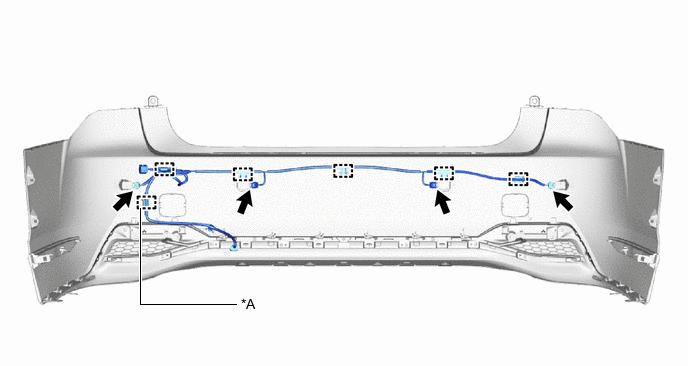
*A w/ Hands Free Power Trunk Lid - -
-
-
INSTALL KICK DOOR CONTROL BRACKET (w/ Hands Free Power Trunk Lid)