LIGHTING SYSTEM Headlight Dimmer Switch Circuit
DESCRIPTION
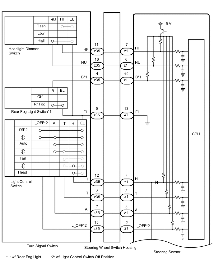
The steering sensor receives the following switch information:
-
Light control switch in off*1, tail, head or AUTO position
-
Headlight dimmer switch in high, low or high flash (pass) position
-
Rear fog light switch in on or off position*2
-
*1: w/ Light Control Switch Off Position
-
*2: w/ Rear Fog Light
WIRING DIAGRAM
Figure 1. for LH Side Type:
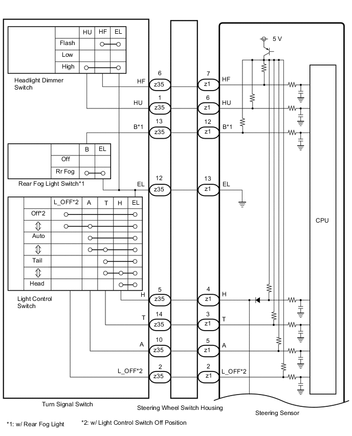
Figure 2. for RH Side Type:
CAUTION / NOTICE / HINT
Note
Before replacing the main body ECU (multiplex network body ECU), refer to Service Bulletin.
PROCEDURE
-
READ VALUE USING GTS
-
Using the GTS, read the Data List.
Chassis > Steering Angle Sensor > Data ListTester Display Measurement Item Range Normal Condition Diagnostic Note Light OFF Switch Light control switch Off position signal OFF or ON OFF: Light control switch not in Off position
ON: Light control switch in Off position
-
-
w/ Light Control Switch Off Position:
-
Although the item is displayed on the GTS, it is not applicable to the vehicle.
w/o Light Control Switch Off Position:
Auto Light Switch Light control switch Auto position signal OFF or ON OFF: Light control switch not in Auto position
ON: Light control switch in Auto position
- Head Light Switch (Tail) Light control switch Tail position signal OFF or ON OFF: Light control switch in neither Tail nor Head position
ON: Light control switch in Tail or Head position
- High Beam Main Switch Headlight dimmer switch High position signal OFF or ON OFF: Headlight dimmer switch not in High position
ON: Headlight dimmer switch in High position
- Passing Light Switch Headlight dimmer switch Flash position signal OFF or ON OFF: Headlight dimmer switch not in Flash position
ON: Headlight dimmer switch in Flash position
- Rear Fog Light/Bad Weather Switch Rear fog light switch signal OFF or ON OFF: Rear fog light switch off
ON: Rear fog light switch on
w/ Rear Fog Light
Chassis > Steering Angle Sensor > Data ListTester Display Light OFF Switch Auto Light Switch Head Light Switch (Tail) High Beam Main Switch Passing Light Switch Rear Fog Light/Bad Weather Switch OK Normal condition listed above are displayed. Result Proceed to OK NG -
NG 
INSPECT TURN SIGNAL SWITCH Click here
OK 
-
-
READ VALUE USING GTS
-
Using the GTS, read the Data List.
Chassis > Steering Angle Sensor > Data ListTester Display Measurement Item Range Normal Condition Diagnostic Note Head Light Switch (Head) Light control switch Head position signal OFF or ON OFF: Light control switch not in Head position
ON: Light control switch in Head position
-
Body Electrical > Main Body > Data ListTester Display Measurement Item Range Normal Condition Diagnostic Note Head Light SW (Head) Light control switch Head position signal OFF or ON OFF: Light control switch not in Head position
ON: Light control switch in Head position
-
Chassis > Steering Angle Sensor > Data ListTester Display Head Light Switch (Head)
Body Electrical > Main Body > Data ListTester Display Head Light SW (Head) OK Normal condition listed above are displayed. Result Result Proceed to OK A NG ("Steering Angle Sensor" side abnormality) B NG ("Main Body" side abnormality) C NG ("Steering Angle Sensor" and "Main Body" are abnormality) D
A 
PROCEED TO NEXT SUSPECTED AREA SHOWN IN PROBLEM SYMPTOMS TABLE Click here
B
REPLACE STEERING SENSOR Click here
D
INSPECT TURN SIGNAL SWITCH Click here
C
-
-
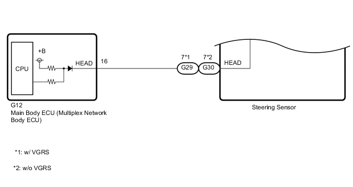
CHECK HARNESS AND CONNECTOR (MAIN BODY ECU [MULTIPLEX NETWORK BODY ECU] - STEERING SENSOR)
-
Disconnect the G12 main body ECU (multiplex network body ECU) connector.
-
Disconnect the G29*1 or G30*2 steering sensor connector.
-
*1: w/ VGRS
-
*2: w/o VGRS
-
-
Measure the resistance according to the value(s) in the table below.
Standard Resistance w/ VGRS Tester Connection Condition Specified Condition G12-16 (HEAD) - G29-7 (HEAD) Always Below 1 Ω w/o VGRS Tester Connection Condition Specified Condition G12-16 (HEAD) - G30-7 (HEAD) Always Below 1 Ω Result Proceed to OK NG
OK
REPLACE MAIN BODY ECU (MULTIPLEX NETWORK BODY ECU) Click here
NG
REPAIR OR REPLACE HARNESS OR CONNECTOR
-
-
INSPECT TURN SIGNAL SWITCH
-
Remove the turn signal switch.
-
Inspect the turn signal switch.
Result Proceed to OK NG
NG
REPLACE TURN SIGNAL SWITCH Click here
OK
-
-
INSPECT STEERING WHEEL SWITCH HOUSING
-
Remove the steering wheel switch housing.
-
Inspect the steering wheel switch housing.
Result Proceed to OK NG
NG
REPLACE STEERING WHEEL SWITCH HOUSING Click here
OK
-
-
CHECK HARNESS AND CONNECTOR (MAIN BODY ECU [MULTIPLEX NETWORK BODY ECU] - STEERING SENSOR)
-
Disconnect the G12 main body ECU (multiplex network body ECU) connector.
-
Disconnect the G29*1 or G30*2 steering sensor connector.
-
*1: w/ VGRS
-
*2: w/o VGRS
-
-
Measure the resistance according to the value(s) in the table below.
Standard Resistance w/ VGRS Tester Connection Condition Specified Condition G12-16 (HEAD) or G29-7 (HEAD) - Body ground Always 10 kΩ or higher w/o VGRS Tester Connection Condition Specified Condition G12-16 (HEAD) or G30-7 (HEAD) - Body ground Always 10 kΩ or higher Result Proceed to OK NG
OK
REPLACE STEERING SENSOR Click here
NG
REPAIR OR REPLACE HARNESS OR CONNECTOR
-
-
INSPECT TURN SIGNAL SWITCH
-
Remove the turn signal switch.
-
Inspect the turn signal switch.
Result Proceed to OK NG
NG
REPLACE TURN SIGNAL SWITCH Click here
OK
-
-
INSPECT STEERING WHEEL SWITCH HOUSING
-
Remove the steering wheel switch housing.
-
Inspect the steering wheel switch housing.
Result Proceed to OK NG
OK
REPLACE STEERING SENSOR Click here
NG
REPLACE STEERING WHEEL SWITCH HOUSING Click here
-