SEAT VIBRATION SYSTEM TERMINALS OF ECU
-
CHECK POSITION CONTROL ECU ASSEMBLY (w/ Front Refreshing Seat)
-
for LHD:
-
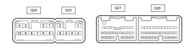
Disconnect the Q27 and Q28 position control ECU assembly connectors.
-
Measure the voltage and resistance according to the value(s) in the table below.
Terminal No. (Symbol) Wiring Color Terminal Description Condition Specified Condition Q27-1 (+B2) - Body ground W - Body ground Auxiliary battery power supply Power switch off 11 to 14 V Q28-1 (GND2) - Body ground W-B - Body ground Ground Always Below 1 Ω Q28-2 (GND1) - Body ground W-B - Body ground Ground Always Below 1 Ω Q28-19 (IG) - Body ground SB - Body ground Ignition power supply Power switch off Below 1 V Power switch on (IG) 11 to 14 V -
Reconnect the Q27 and Q28 position control ECU assembly connectors.
-
Measure the voltage and resistance according to the value(s) in the table below.
Terminal No. (Symbol) Wiring Color Terminal Description Condition Specified Condition Q28-3 (POMG) - Body ground W-B - Body ground Ground Always Below 1 Ω Q28-3 (POMG) - Q28-4 (POM) W-B - V Lumbar support pump sub-assembly operation Lumbar support pump sub-assembly operating 11 to 14 V Q28-7 (LIN) - Body ground SB - Body ground LIN communication line Power switch on (IG) Pulse generation
-
-
for RHD:

-
Disconnect the Q7 and Q8 position control ECU assembly connectors.
-
Measure the voltage and resistance according to the value(s) in the table below.
Terminal No. (Symbol) Wiring Color Terminal Description Condition Specified Condition Q7-1 (+B2) - Body ground W - Body ground Auxiliary battery power supply Power switch off 11 to 14 V Q8-1 (GND2) - Body ground W-B - Body ground Ground Always Below 1 Ω Q8-2 (GND1) - Body ground W-B - Body ground Ground Always Below 1 Ω Q8-19 (IG) - Body ground SB - Body ground Ignition power supply Power switch off Below 1 V Power switch on (IG) 11 to 14 V -
Reconnect the Q7 and Q8 position control ECU assembly connectors.
-
Measure the voltage and resistance according to the value(s) in the table below.
Terminal No. (Symbol) Wiring Color Terminal Description Condition Specified Condition Q8-3 (POMG) - Body ground W-B - Body ground Ground Always Below 1 Ω Q8-3 (POMG) - Q8-4 (POM) W-B - V Lumbar support pump sub-assembly operation Lumbar support pump sub-assembly operating 11 to 14 V Q8-7 (LIN) - Body ground SB - Body ground LIN communication line Power switch on (IG) Pulse generation
-
-
-
CHECK NO. 2 POSITION CONTROL ECU ASSEMBLY (w/ Front Refreshing Seat)
-
for LHD:
-
Disconnect the R6 and R7 No. 2 position control ECU assembly onnectors.
-
Measure the voltage and resistance according to the value(s) in the table below.
Terminal No. (Symbol) Wiring Color Terminal Description Condition Specified Condition Q7-1 (+B2) - Body ground W - Body ground Auxiliary battery power supply Power switch off 11 to 14 V Q8-1 (GND2) - Body ground W-B - Body ground Ground Always Below 1 Ω Q8-2 (GND1) - Body ground W-B - Body ground Ground Always Below 1 Ω Q8-19 (IG) - Body ground SB - Body ground Ignition power supply Power switch off Below 1 V Power switch on (IG) 11 to 14 V -
Reconnect the Q27 and Q28 No. 2 position control ECU assembly connectors.
-
Measure the voltage and resistance according to the value(s) in the table below.
Terminal No. (Symbol) Wiring Color Terminal Description Condition Specified Condition Q8-3 (POMG) - Body ground W-B - Body ground Ground Always Below 1 Ω Q8-3 (POMG) - Q8-4 (POM) W-B - V Lumbar support pump sub-assembly operation Lumbar support pump sub-assembly operating 11 to 14 V Q8-7 (LIN) - Body ground SB - Body ground LIN communication line Power switch on (IG) Pulse generation
-
-
for RHD:
-
Disconnect the Q27 and Q28 No. 2 position control ECU assembly connectors.
-
Measure the voltage and resistance according to the value(s) in the table below.
Terminal No. (Symbol) Wiring Color Terminal Description Condition Specified Condition Q27-1 (+B2) - Body ground W - Body ground Auxiliary battery power supply Power switch off 11 to 14 V Q28-1 (GND2) - Body ground W-B - Body ground Ground Always Below 1 Ω Q28-2 (GND1) - Body ground W-B - Body ground Ground Always Below 1 Ω Q28-19 (IG) - Body ground SB - Body ground Ignition power supply Power switch off Below 1 V Power switch on (IG) 11 to 14 V -
Reconnect the Q27 and Q28 No. 2 position control ECU assembly connectors.
-
Measure the voltage and resistance according to the value(s) in the table below.
Terminal No. (Symbol) Wiring Color Terminal Description Condition Specified Condition Q28-3 (POMG) - Body ground W-B - Body ground Ground Always Below 1 Ω Q28-3 (POMG) - Q28-4 (POM) W-B - V Lumbar support pump sub-assembly operation Lumbar support pump sub-assembly operating 11 to 14 V Q28-7 (LIN) - Body ground SB - Body ground LIN communication line Power switch on (IG) Pulse generation
-
-
-
CHECK POSITION CONTROL ECU ASSEMBLY LH
-
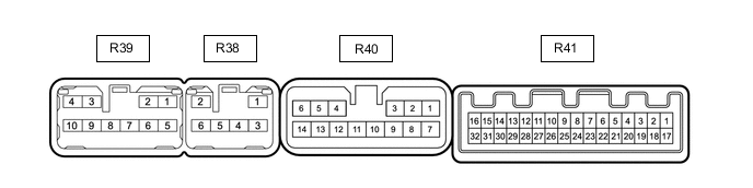
Disconnect the R40 and R41 position control ECU assembly LH connectors.
-
Measure the voltage and resistance according to the value(s) in the table below.
Terminal No. (Symbol) Wiring Color Terminal Description Condition Specified Condition R40-8 (GND2) - Body ground W-B - Body ground Ground Always Below 1 Ω R40-9 (GND1) - Body ground W-B - Body ground Ground Always Below 1 Ω R40-12 (+B3) - Body ground W - Body ground Auxiliary battery power supply Power switch off 11 to 14 V R41-15 (IG) - Body ground LG - Body ground Ignition power supply Power switch off Below 1 V Power switch on (IG) 11 to 14 V -
Reconnect the R40 and R41 position control ECU assembly LH connectors.
-
Measure the voltage and resistance according to the value(s) in the table below.
Terminal No. (Symbol) Wiring Color Terminal Description Condition Specified Condition R40-10 (POM) - R40-11 (POMG) B - R Lumbar support pump sub-assembly operation Lumbar support pump sub-assembly operating 11 to 14 V R40-11 (POMG) - Body ground R - Body ground Ground Always Below 1 Ω R41-2 (LINM) - Body ground BR - Body ground LIN communication line Power switch on (IG) Pulse generation R40-2 (HT2) - R40-5 (HTG2) G - LG Heater power supply Heating massage function ON 19.8 to 24.2 Ω R40-3 (HT1) - R40-6 (HTG1) R - P Heater power supply Heating massage function ON 19.8 to 24.2 Ω R40-4 (NTC3) - R40-7 (SGND) L - BR Thermistor input signal Heating massage function ON 25°C: 8 kΩ R40-6 (NTC1) - R40-7 (SGND) R - BR Thermistor input signal Heating massage function ON 25°C: 8 kΩ R40-7 (SGND) - Body ground BR - Body ground Ground Always Below 1 Ω R40-22 (NTC4) - R40-7 (SGND) GR - BR Thermistor input signal Heating massage function ON 25°C: 8 kΩ R40-23 (NTC2) - R40-7 (SGND) B - R Thermistor input signal Heating massage function ON 25°C: 8 kΩ R41-3 (BCL1) - Body ground R - Body ground Rear RH seat belt buckle switch signal Rear RH seat belt fastened 10 kΩ or higher Rear RH seat belt unfastened Below 1 Ω R41-17 (ODS) - Body ground BR - Body ground Occupant detection sensor signal Rear seat RH occupied Below 100 Ω Rear seat RH not occupied 1 MΩ or higher
-
-
CHECK POSITION CONTROL ECU ASSEMBLY RH
-
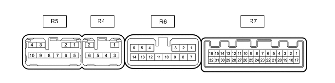
Disconnect the R6 and R7 position control ECU assembly RH connectors.
-
Measure the voltage and resistance according to the value(s) in the table below.
Terminal No. (Symbol) Wiring Color Terminal Description Condition Specified Condition R6-8 (GND2) - Body ground W-B - Body ground Ground Always Below 1 Ω R6-9 (GND1) - Body ground W-B - Body ground Ground Always Below 1 Ω R6-12 (+B3) - Body ground W - Body ground Auxiliary battery power supply Power switch off 11 to 14 V R7-15 (IG) - Body ground LG - Body ground Ignition power supply Power switch off Below 1 V Power switch on (IG) 11 to 14 V -
Reconnect the R6 and R7 position control ECU assembly RH connectors.
-
Measure the voltage and resistance according to the value(s) in the table below.
Terminal No. (Symbol) Wiring Color Terminal Description Condition Specified Condition R6-10 (POM) - R6-11 (POMG) B - R Lumbar support pump sub-assembly operation Lumbar support pump sub-assembly operating 11 to 14 V R6-11 (POMG) - Body ground R - Body ground Ground Always Below 1 Ω R7-2 (LINM) - Body ground BR - Body ground LIN communication line Power switch on (IG) Pulse generation R6-2 (HT2) - R6-5 (HTG2) G - LG Heater power supply Heating massage function ON 19.8 to 24.2 Ω R6-3 (HT1) - R6-6 (HTG1) R - P Heater power supply Heating massage function ON 19.8 to 24.2 Ω R6-4 (NTC3) - R6-7 (SGND) L - BR Thermistor input signal Heating massage function ON 25°C: 8 kΩ R6-6 (NTC1) - R6-7 (SGND) R - BR Thermistor input signal Heating massage function ON 25°C: 8 kΩ R6-7 (SGND) - Body ground BR - Body ground Ground Always Below 1 Ω R6-22 (NTC4) - R6-7 (SGND) GR - BR Thermistor input signal Heating massage function ON 25°C: 8 kΩ R6-23 (NTC2) - R6-7 (SGND) B - R Thermistor input signal Heating massage function ON 25°C: 8 kΩ R7-3 (BCL1) - Body ground R - Body ground Rear RH seat belt buckle switch signal Rear RH seat belt fastened 10 kΩ or higher Rear RH seat belt unfastened Below 1 Ω R7-17 (ODS) - Body ground BR - Body ground Occupant detection sensor signal Rear seat RH occupied Below 100 Ω Rear seat RH not occupied 1 MΩ or higher
-