REAR POWER SEAT CONTROL SYSTEM TERMINALS OF ECU
-
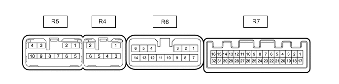
POSITION CONTROL ECU ASSEMBLY RH
-
Disconnect the R6 and R7 position control ECU assembly RH connectors.
-
Measure the resistance and voltage according to the value(s) in the table below.
Terminal No. (Symbol) Wiring Color Terminal Description Condition Specified Condition R6-8 (GND2) - Body ground W-B - Body ground Ground Always Below 1 Ω R6-9 (GND1) - Body ground W-B - Body ground Ground Always Below 1 Ω R6-12 (+B3) - Body ground W - Body ground Auxiliary battery power supply Power switch off 11 to 14 V R6-13 (+B2) - Body ground W - Body ground Auxiliary battery power supply Power switch off 11 to 14 V R6-14 (+B1) - Body ground W - Body ground Auxiliary battery power supply Power switch off 11 to 14 V R6-16 (SYSB) - Body ground BR - Body ground Auxiliary battery power supply Power switch off 11 to 14 V R7-15 (IG) - Body ground BR - Body ground Ignition power supply Power switch off - Power switch on (IG) Below 1 V → 11 to 14 V R7-28 (SYSG) - Body ground W-B - Body ground Ground Always Below 1 Ω -
Reconnect the R6 and R7 position control ECU assembly RH connectors.
-
Measure the resistance and voltage, check for waveform according to the value(s) in the table below.
Terminal No. (Symbol) Wiring Color Terminal Description Condition Specified Condition R4-1 (OTE-) - Body ground* R - Body ground Ottoman long/short motor signal (short) Ottoman switch off Below 1 V Ottoman switch on (short) 11 to 14 V R4-2 (FRV-) - Body ground R - Body ground Front tilt motor signal (downward) Front vertical switch off Below 1 V Front vertical switch on (downward) 11 to 14 V R4-3 (HD-) - Body ground R - Body ground Headrest front/rear motor signal (rearward) Headrest switch off Below 1 V Headrest switch on (rearward) 11 to 14 V R4-4 (OTG-) - Body ground* R - Body ground Ottoman up/down motor signal (down) Ottoman switch off Below 1 V Ottoman switch on (down) 11 to 14 V R4-5 (H-) - Body ground R - Body ground Headrest up/down motor signal (downward) Headrest switch off Below 1 V Headrest switch on (downward) 11 to 14 V R4-6 (RCL-) - Body ground* G - Body ground Reclining motor signal (rearward) Reclining switch off Below 1 V Reclining switch on (rearward) 11 to 14 V R5-1 (SLD+) - Body ground GR - Body ground Slide motor signal (forward) Slide switch off Below 1 V Slide switch on (forward) 11 to 14 V R5-3 (OTE+) - Body ground* B - Body ground Ottoman long/short motor signal (long) Ottoman switch off Below 1 V Ottoman switch on (long) 11 to 14 V R5-4 (FRV+) - Body ground B - Body ground Front tilt motor signal (upward) Front vertical switch off Below 1 V Front vertical switch on (upward) 11 to 14 V R5-6 (SLD-) - Body ground L - Body ground Slide motor signal (rearward) Slide switch off Below 1 V Slide switch on (rearward) 11 to 14 V R5-7 (HD+) - Body ground B - Body ground Headrest front/rear motor signal (forward) Headrest switch off Below 1 V Headrest switch on (forward) 11 to 14 V R5-8 (OTG+) - Body ground* B - Body ground Ottoman up/down motor signal (up) Ottoman switch off Below 1 V Ottoman switch on (up) 11 to 14 V R5-9 (H+) - Body ground B - Body ground Headrest up/down motor signal (upward) Headrest switch off Below 1 V Headrest switch on (upward) 11 to 14 V R5-10 (RCL+) - Body ground* R - Body ground Reclining motor signal (forward) Reclining switch off Below 1 V Reclining switch on (forward) 11 to 14 V R7-1 (LINS) - Body ground GR - Body ground LIN communication line Power switch on (IG) Pulse generation R7-2 (LINM) - Body ground BR - Body ground LIN communication line Power switch on (IG) Pulse generation R7-7 (SGND) - Body ground BR - Body ground Sensor ground Always Below 1 Ω R7-10 (SOTE) - Body ground* P - Body ground Ottoman position signal Ottoman long/short motor operating 4.8 to 5.1 V R7-11 (SSFV) - Body ground L - Body ground Front vertical position signal Front tilt motor operating 4.8 to 5.1 V R7-12 (SSRS) - Body ground G - Body ground Slide position signal Slide motor operating 4.8 to 5.1 V R7-13 (SSRR) - Body ground L - Body ground Reclining position signal Reclining motor operating 4.8 to 5.1 V R7-25 (SSHD) - Body ground P - Body ground Headrest position signal Headrest front/rear motor operating 4.8 to 5.1 V R7-26 (SSRH) - Body ground P - Body ground Headrest position signal Headrest up/down motor operating 4.8 to 5.1 V R7-27 (SOTG) - Body ground* P - Body ground Ottoman position signal Ottoman long/short motor operating 4.8 to 5.1 V R7-30 (PVC2) - Body ground* V - Body ground Reclining position signal Reclining motor operating 4.8 to 5.1 V
-
*: w/ Ottoman (for LHD)
-
-
-
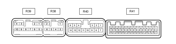
POSITION CONTROL ECU ASSEMBLY LH
-
Disconnect the R40 and R41 position control ECU assembly LH connectors.
-
Measure the resistance and voltage according to the value(s) in the table below.
Terminal No. (Symbol) Wiring Color Terminal Description Condition Specified Condition R40-8 (GND2) - Body ground W-B - Body ground Ground Always Below 1 Ω R40-9 (GND1) - Body ground W-B - Body ground Ground Always Below 1 Ω R40-12 (+B3) - Body ground W - Body ground Auxiliary battery power supply Power switch off 11 to 14 V R40-13 (+B2) - Body ground W - Body ground Auxiliary battery power supply Power switch off 11 to 14 V R40-14 (+B1) - Body ground W - Body ground Auxiliary battery power supply Power switch off 11 to 14 V R40-16 (SYSB) - Body ground BR - Body ground Auxiliary battery power supply Power switch off 11 to 14 V R41-15 (IG) - Body ground BR - Body ground Ignition power supply Power switch off - Power switch on (IG) Below 1 V → 11 to 14 V R41-28 (SYSG) - Body ground W-B - Body ground Ground Always Below 1 Ω -
Reconnect the R40 and R41 position control ECU assembly LH connectors.
-
Measure the resistance and voltage, check for waveform according to the value(s) in the table below.
Terminal No. (Symbol) Wiring Color Terminal Description Condition Specified Condition R38-1 (OTE-) - Body ground* R - Body ground Ottoman long/short motor signal (short) Ottoman switch off Below 1 V Ottoman switch on (short) 11 to 14 V R38-2 (FRV-) - Body ground R - Body ground Front tilt motor signal (downward) Front vertical switch off Below 1 V Front vertical switch on (downward) 11 to 14 V R38-3 (HD-) - Body ground R - Body ground Headrest front/rear motor signal (rearward) Headrest switch off Below 1 V Headrest switch on (rearward) 11 to 14 V R38-4 (OTG-) - Body ground* R - Body ground Ottoman up/down motor signal (down) Ottoman switch off Below 1 V Ottoman switch on (down) 11 to 14 V R38-5 (H-) - Body ground R - Body ground Headrest up/down motor signal (downward) Headrest switch off Below 1 V Headrest switch on (downward) 11 to 14 V R38-6 (RCL-) - Body ground* G - Body ground Reclining motor signal (rearward) Reclining switch off Below 1 V Reclining switch on (rearward) 11 to 14 V R39-1 (SLD+) - Body ground GR - Body ground Slide motor signal (forward) Slide switch off Below 1 V Slide switch on (forward) 11 to 14 V R39-3 (OTE+) - Body ground* B - Body ground Ottoman long/short motor signal (long) Ottoman switch off Below 1 V Ottoman switch on (long) 11 to 14 V R39-4 (FRV+) - Body ground B - Body ground Front tilt motor signal (upward) Front vertical switch off Below 1 V Front vertical switch on (upward) 11 to 14 V R39-6 (SLD-) - Body ground L - Body ground Slide motor signal (rearward) Slide switch off Below 1 V Slide switch on (rearward) 11 to 14 V R39-7 (HD+) - Body ground B - Body ground Headrest front/rear motor signal (forward) Headrest switch off Below 1 V Headrest switch on (forward) 11 to 14 V R39-8 (OTG+) - Body ground* B - Body ground Ottoman up/down motor signal (upward) Ottoman switch off Below 1 V Ottoman switch on (up) 11 to 14 V R39-9 (H+) - Body ground B - Body ground Headrest up/down motor signal (upward) Headrest switch off Below 1 V Headrest switch on (upward) 11 to 14 V R39-10 (RCL+) - Body ground* R - Body ground Reclining motor signal (forward) Reclining switch off Below 1 V Reclining switch on (forward) 11 to 14 V R41-1 (LINS) - Body ground GR - Body ground LIN communication line Power switch on (IG) Pulse generation R41-2 (LINM) - Body ground BR - Body ground LIN communication line Power switch on (IG) Pulse generation R41-7 (SGND) - Body ground BR - Body ground Sensor ground Always Below 1 Ω R41-10 (SOTE) - Body ground* P - Body ground Ottoman position signal Ottoman long/short motor operating 4.8 to 5.1 V R41-11 (SSFV) - Body ground L - Body ground Front vertical position signal Front tilt motor operating 4.8 to 5.1 V R41-12 (SSRS) - Body ground G - Body ground Slide position signal Slide motor operating 4.8 to 5.1 V R41-13 (SSRR) - Body ground L - Body ground Reclining position signal Reclining motor operating 4.8 to 5.1 V R41-25 (SSHD) - Body ground P - Body ground Headrest position signal Headrest front/rear motor operating 4.8 to 5.1 V R41-26 (SSRH) - Body ground P - Body ground Headrest position signal Headrest up/down motor operating 4.8 to 5.1 V R41-27 (SOTG) - Body ground* P - Body ground Ottoman position signal Ottoman long/short motor operating 4.8 to 5.1 V R41-30 (PVC2) - Body ground* V - Body ground Reclining position signal Reclining motor operating 4.8 to 5.1 V
-
*: w/ Ottoman (for RHD)
-
-