| DTC Code | DTC Name |
|---|---|
| One or more Power Seat Motors do not Operate |
DESCRIPTION
Signals are input into the position control ECU assembly. The built-in ECU manages the signals received from the position control ECU assembly, and operates each motorand each bladder. If the position control ECU assembly receives more than 2 motor or bladder operation signals, the motor or bladder is stopped. Manual operation is restarted after the position control ECU assembly receives 1 signal only.
WIRING DIAGRAM
Click here
-
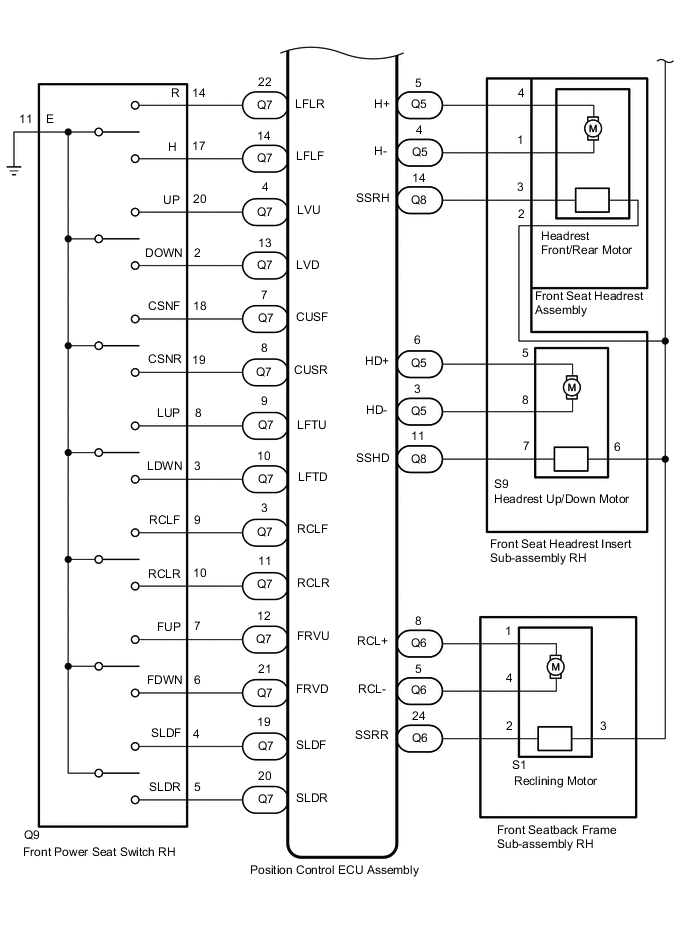 Figure 2. for RHD:
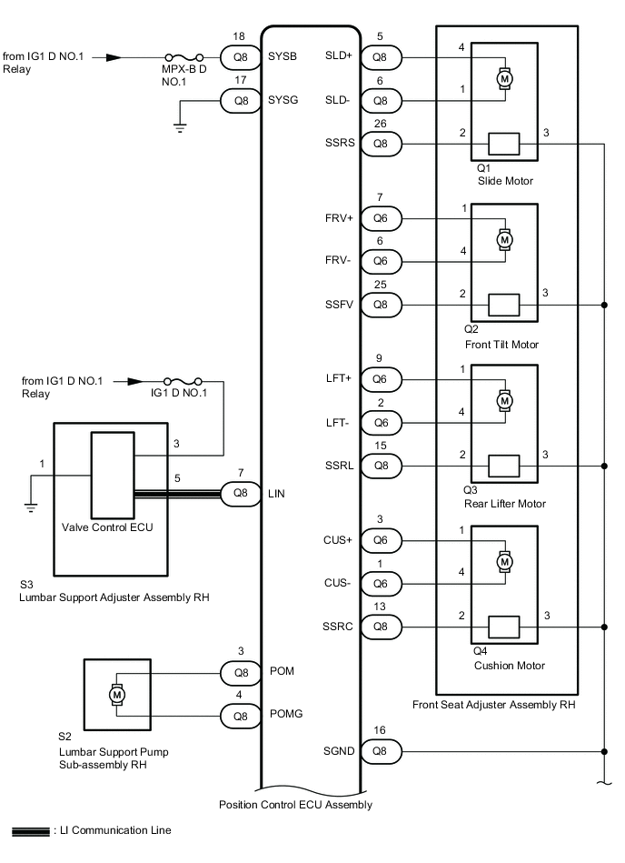
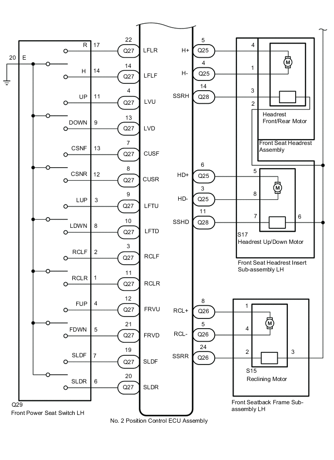 Figure 1. for LHD:
for Driver Seat:
-
Figure 4. for RHD:
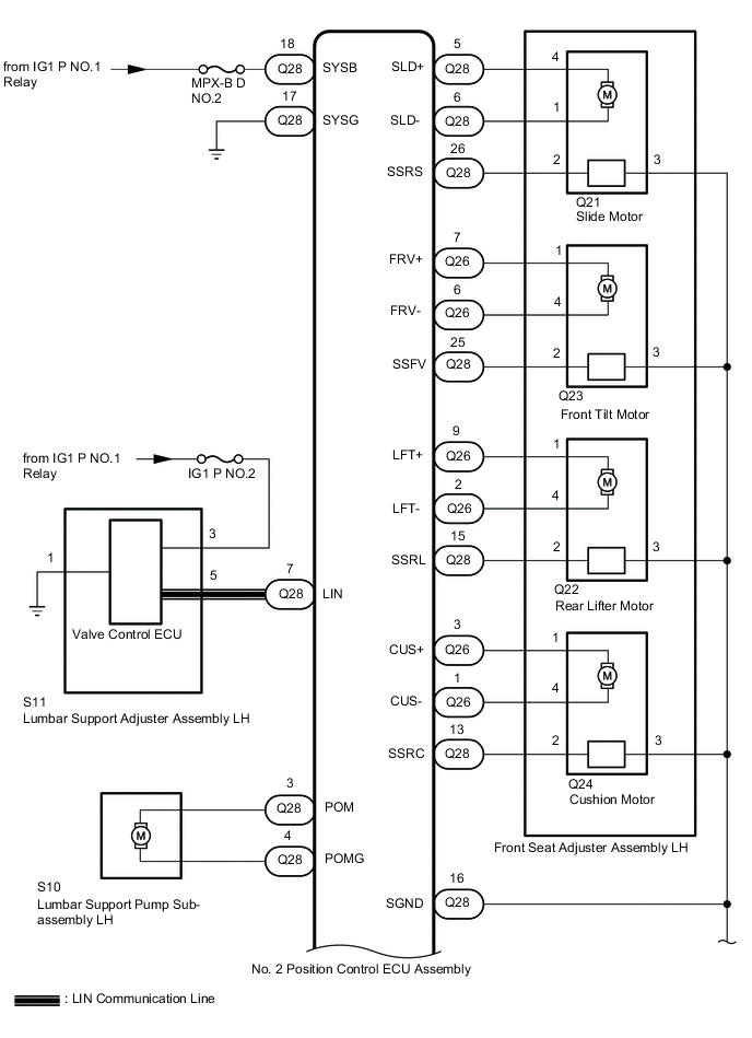
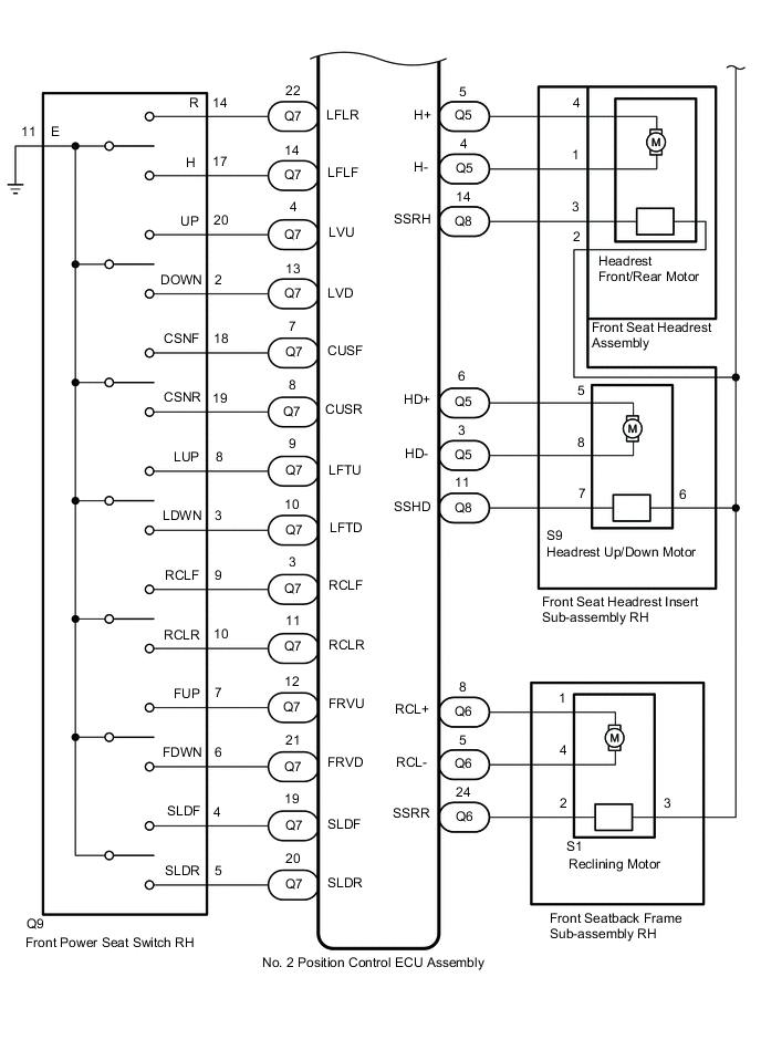 Figure 3. for LHD:
for Front Passenger Seat
CAUTION / NOTICE / HINT
-
Inspect the fuses for circuits related to this system before performing the following procedure.
-
Initializing the position control ECU assembly will clear the seat position memory.
-
Make sure to initialize the position control ECU assembly after replacing the seat assembly or any related parts (including removal and installation).
-
Before initializing the seat ECU, make sure that the D/C CUT fuse is normal.
-
When any of the following conditions are met, the seat position Information in the position control ECU assembly will be cleared.
-
-
The power switch is turned off with any of the seat switches being operated and the D/C CUT fuse removed.
-
The power switch is turned off within 1 second of any of the seat switches being operated with the D/C CUT fuse removed.
-
PROCEDURE
- Click here
CHECK FRONT POWER SEAT OPERATION
-
Check that each function of the power seat operates normally by using the front power seat switch.
Result Result Proceed to Driver power seat functions do not operate A Front passenger power seat functions do not operate B
-
- Click here
CHECK FRONT POWER SEAT OPERATION
-
Check that each function of the power seat operates normally by using the front power seat switch.
Result Result Proceed to One or more power seat functions do not operate A All power seat functions do not operate B
- AClick here
- B
GO TO OTHER DIAGNOSTIC PROCEDURE (Front Power Seat does not Operate with Front Power Seat Switch)Click here
-
- Click here
READ VALUE USING GTS (POWER SEAT SWITCH)
-
Connect the GTS to the DLC3.
-
Turn the power switch on (IG).
-
Turn the GTS on.
-
Enter the following menus: Body Electrical / Driver Seat / Data List.
-
Read the Data List according to the display on the GTS.
- Body Electrical > Driver Seat > Data List
Tester Display Measurement Item Range Normal Condition Diagnostic Note Reclining Rear Reclining switch signal (rearward) ON or OFF ON: Reclining switch (rearward) on
OFF: Reclining switch (rearward) off
- Reclining Front Reclining switch signal (forward) ON or OFF ON: Reclining switch (forward) on
OFF: Reclining switch (forward) off
- Front Vertical Down Front vertical switch signal (downward) ON or OFF ON: Front vertical switch (downward) on
OFF: Front vertical switch (downward) off
- Front Vertical Up Front vertical switch signal (upward) ON or OFF ON: Front vertical switch (upward) on
OFF: Front vertical switch (upward) off
- Lifter Switch Down Lifter switch signal (downward) ON or OFF ON: Lifter switch (downward) on
OFF: Lifter switch (downward) off
- Lifter Switch Up Lifter switch signal (upward) ON or OFF ON: Lifter switch (upward) on
OFF: Lifter switch (upward) off
- Slide Rear Slide switch signal (rearward) ON or OFF ON: Slide switch (rearward) on
OFF: Slide switch (rearward) off
- Slide Front Slide switch signal (forward) ON or OFF ON: Slide switch (forward) on
OFF: Slide switch (forward) off
- Lumbar Switch UP Lumbar support adjuster switch signal (upward) ON or OFF ON: Lumbar support adjuster switch (upward) on
OFF: Lumbar support adjuster switch (upward) off
- Lumbar Switch Down Lumbar support adjuster switch signal (downward) ON or OFF ON: Lumbar support adjuster switch (downward) on
OFF: Lumbar support adjuster switch (downward) off
- Lumbar Switch Front Lumbar support adjuster switch signal (forward) ON or OFF ON: Lumbar support adjuster switch (forward) on
OFF: Lumbar support adjuster switch (forward) off
- Lumbar Switch Rear Lumbar support adjuster switch signal (rearward) ON or OFF ON: Lumbar support adjuster switch (rearward) on
OFF: Lumbar support adjuster switch (rearward) off
- Cushion Length Front Cushion length switch signal (forward) ON or OFF ON: Cushion length switch (forward) on
OFF: Cushion length switch (forward) off
- Cushion Length Rear Cushion length switch signal (rearward) ON or OFF ON: Cushion length switch (rearward) on
OFF: Cushion length switch (rearward) off
- -
-
- Body Electrical > Driver Seat > Data List
Tester Display Reclining Rear Reclining Front Front Vertical Down Front Vertical Up Lifter Switch Down Lifter Switch Up Slide Rear Slide Front Lumbar Switch UP Lumbar Switch Down Lumbar Switch Front Lumbar Switch Rear Cushion Length Front Cushion Length Rear -
-
-
-
OK ON or OFF is displayed on the GTS according to the table above. Result Proceed to OK NG - Body Electrical > Driver Seat > Data List
- OKClick here
- NGClick here
GO TO STEP 6
-
- Click here
PERFORM ACTIVE TEST USING GTS (POWER SEAT MOTOR)
-
Enter the following menus: Body Electrical / Driver Seat / Active Test.
-
Perform the Active Test according to the display on the GTS.
- Body Electrical > Driver Seat > Active Test
Tester Display Measurement Item Control Range Diagnostic Note Seat Reclining Seat reclining operation OFF/Rear/Front - Front Vertical Operation Seat front vertical operation OFF/Down/Up - Lifter Operation Seat lifter operation OFF/Down/Up - Seat Slide Operation Seat slide operation OFF/Rear/Front - Cushion Length Seat cushion length operation OFF/Rear/Front - Headrest Operation Headrest up/down operation OFF/Down/Up - Headrest Front/Rear Headrest front/rear operation OFF/Rear/Front - Lumbar Upper Pneumatic support function (lumbar upper) operation OFF/Intake/Exhaust - Lumbar Middle Pneumatic support function (lumbar middle) operation OFF/Intake/Exhaust - Lumbar Bottom Pneumatic support function (lumbar bottom) operation OFF/Intake/Exhaust - Lower Back Pneumatic support function (lower back) operation OFF/Intake/Exhaust - Lower Cushion Pneumatic support function (lower cushion) operation OFF/Intake/Exhaust - Shoulder Pneumatic support function (shoulder) operation OFF/Intake/Exhaust - Side Back Support Pneumatic support function (side back) operation OFF/Intake/Exhaust - Side Cushion Support Pneumatic support function (side cushion) operation OFF/Intake/Exhaust - -
-
- Body Electrical > Driver Seat > Active Test
Tester Display Seat Reclining -
-
-
-
- Body Electrical > Driver Seat > Active Test
Tester Display Front Vertical Operation -
-
-
-
- Body Electrical > Driver Seat > Active Test
Tester Display Lifter Operation -
-
-
-
- Body Electrical > Driver Seat > Active Test
Tester Display Seat Slide Operation -
-
-
-
- Body Electrical > Driver Seat > Active Test
Tester Display Cushion Length -
-
-
-
- Body Electrical > Driver Seat > Active Test
Tester Display Headrest Operation -
-
-
-
- Body Electrical > Driver Seat > Active Test
Tester Display Headrest Front/Rear -
-
-
-
- Body Electrical > Driver Seat > Active Test
Tester Display Lumbar Upper -
-
-
-
- Body Electrical > Driver Seat > Active Test
Tester Display Lumbar Middle -
-
-
-
- Body Electrical > Driver Seat > Active Test
Tester Display Lumbar Bottom -
-
-
-
- Body Electrical > Driver Seat > Active Test
Tester Display Lower Back -
-
-
-
- Body Electrical > Driver Seat > Active Test
Tester Display Lower Cushion -
-
-
-
- Body Electrical > Driver Seat > Active Test
Tester Display Shoulder -
-
-
-
- Body Electrical > Driver Seat > Active Test
Tester Display Side Back Support -
-
-
-
- Body Electrical > Driver Seat > Active Test
Tester Display Side Cushion Support -
-
-
-
Result Result Proceed to The power seat functions operate normally. A Slide, front vertical, rear lifter or cushon length function does not operate normally. B Reclining function does not operate normally. C Headrest adjuster function does not operate normally. D Lumbar support function does not operate normally. E - Body Electrical > Driver Seat > Active Test
- A
REPLACE POSITION CONTROL ECU ASSEMBLYClick here
- BClick here
- CClick here
- DClick here
- EClick here
-
- Click here
INSPECT FRONT SEAT ADJUSTER ASSEMBLY (SLIDE, FRONT TILT, REAR LIFTER, CUSHION MOTOR)
-
Remove the front seat adjuster assembly (slide, front tilt, rear lifter, cushion motor).
-
Inspect the front seat adjuster assembly (slide, front tilt, rear lifter, cushion motor).
Result Proceed to OK NG
- OKClick here
- NG
REPLACE FRONT SEAT ADJUSTER ASSEMBLYClick here
-
- Click here
INSPECT FRONT POWER SEAT SWITCH
-
Remove the front power seat switch.
-
Inspect the front power seat switch.
Result Proceed to OK NG
- OKClick here
- NG
REPLACE FRONT POWER SEAT SWITCHClick here
-
- Click here
CHECK HARNESS OR CONNECTOR (POSITION CONTROL ECU ASSEMBLY - FRONT POWER SEAT SWITCH)
-
for LHD:
-
Disconnect the position control ECU assembly connector.
-
Measuer the resistance according to the value(s) in the table below.
Standard Resistance Tester Connection Condition Specified Condition Q28-17 (SYSG) - Body ground Always Below 1 Ω -
Measuer the voltagee according to the value(s) in the table below.
Standard Voltage Tester Connection Condition Specified Condition Q28-18 (SYSB) - Body ground Power switch off 11 to 14 V
-
-
for RHD:
-
Disconnect the position control ECU assembly connector.
-
Measuer the resistance according to the value(s) in the table below.
Standard Resistance Tester Connection Condition Specified Condition Q8-17 (SYSG) - Body ground Always Below 1 Ω -
Measuer the voltagee according to the value(s) in the table below.
Standard Voltage Tester Connection Condition Specified Condition Q8-18 (SYSB) - Body ground Power switch off 11 to 14 V
Result Proceed to OK NG -
- OKClick here
- NG
REPAIR OR REPLACE HARNESS OR CONNECTOR
-
- Click here
CHECK HARNESS OR CONNECTOR (POSITION CONTROL ECU ASSEMBLY - FRONT POWER SEAT SWITCH)
-
for LHD:
-
Disconnect the Q27 position control ECU assembly connector.
-
Disconnect the Q29 front power saet switch LH connector.
-
Measuer the resistance according to the value(s) in the table below.
Standard Resistance Tester Connection Condition Specified Condition Q27-20 (SLDR) - Q29-6 (SLDR) Always Below 1 Ω Q27-20 (SLDR) or Q29-6 (SLDR) - Other terminals and body ground Always 10 kΩ or higher Q27-19 (SLDF) - Q29-7 (SLDF) Always Below 1 Ω Q27-19 (SLDF) or Q29-7 (SLDF) - Other terminals and body ground Always 10 kΩ or higher Q27-11 (RCLR) - Q29-1 (RCLR) Always Below 1 Ω Q27-11 (RCLR) or Q29-1 (RCLR) - Other terminals and body ground Always 10 kΩ or higher Q27-3 (RCLF) - Q29-2 (RCLF) Always Below 1 Ω Q27-3 (RCLF) or Q29-2 (RCLF) - Other terminals and body ground Always 10 kΩ or higher Q27-12 (FRVU) - Q29-4 (FUP) Always Below 1 Ω Q27-12 (FRVU) or Q29-4 (FUP) - Other terminals and body ground Always 10 kΩ or higher Q27-12 (FRVD) - Q29-5 (FDWN) Always Below 1 Ω Q27-12 (FRVD) or Q29-5 (FDWN) - Other terminals and body ground Always 10 kΩ or higher Q27-9 (LFTU) - Q29-3 (LUP) Always Below 1 Ω Q27-9 (LFTU) or Q29-3 (LUP) - Other terminals and body ground Always 10 kΩ or higher Q27-10 (LFTD) - Q29-8 (LDWN) Always Below 1 Ω Q27-10 (LFTD) or Q29-8 (LDWN) - Other terminals and body ground Always 10 kΩ or higher Q27-14 (LFLF) - Q29-14 (H) Always Below 1 Ω Q27-14 (LFLF) or Q29-14 (H) - Other terminals and body ground Always 10 kΩ or higher Q27-22 (LFLR) - Q29-17 (R) Always Below 1 Ω Q27-22 (LFLR) or Q29-17 (R) - Other terminals and body ground Always 10 kΩ or higher Q27-4 (LVU) - Q29-11 (H1) Always Below 1 Ω Q27-4 (LVU) or Q29-11 (H1) - Other terminals and body ground Always 10 kΩ or higher Q27-13 (LVD) - Q29-9 (R1) Always Below 1 Ω Q27-13 (LVD) or Q29-9 (R1) - Other terminals and body ground Always 10 kΩ or higher Q27-7 (CUSF) - Q29-13 (CSNF) Always Below 1 Ω Q27-7 (CUSF) or Q29-13 (CSNF) - Other terminals and body ground Always 10 kΩ or higher Q27-8 (CUSR) - Q29-12 (CSNR) Always Below 1 Ω Q27-8 (CUSR) or Q29-12 (CSNR) - Other terminals and body ground Always 10 kΩ or higher
-
-
for RHD:
-
Disconnect the Q7 position control ECU assembly connector.
-
Disconnect the Q9 front power saet switch RH connector.
-
Measuer the resistance according to the value(s) in the table below.
Standard Resistance Tester Connection Condition Specified Condition Q7-20 (SLDR) - Q9-5 (SLDR) Always Below 1 Ω Q7-20 (SLDR) or Q9-5 (SLDR) - Other terminals and body ground Always 10 kΩ or higher Q7-19 (SLDF) - Q9-4 (SLDF) Always Below 1 Ω Q7-19 (SLDF) or Q9-4 (SLDF) - Other terminals and body ground Always 10 kΩ or higher Q7-11 (RCLR) - Q9-10 (RCLR) Always Below 1 Ω Q7-11 (RCLR) or Q9-10 (RCLR) - Other terminals and body ground Always 10 kΩ or higher Q7-3 (RCLF) - Q9-9 (RCLF) Always Below 1 Ω Q7-3 (RCLF) or Q9-9 (RCLF) - Other terminals and body ground Always 10 kΩ or higher Q7-12 (FRVU) - Q9-7 (FUP) Always Below 1 Ω Q7-12 (FRVU) or Q9-7 (FUP) - Other terminals and body ground Always 10 kΩ or higher Q7-20 (FRVD) - Q9-6 (FDWN) Always Below 1 Ω Q7-20 (FRVD) or Q9-6 (FDWN) - Other terminals and body ground Always 10 kΩ or higher Q7-9 (LFTU) - Q9-8 (LUP) Always Below 1 Ω Q7-9 (LFTU) or Q9-8 (LUP) - Other terminals and body ground Always 10 kΩ or higher Q7-10 (LFTD) - Q9-3 (LDWN) Always Below 1 Ω Q7-10 (LFTD) or Q9-3 (LDWN) - Other terminals and body ground Always 10 kΩ or higher Q7-14 (LFLF) - Q9-17 (H) Always Below 1 Ω Q7-14 (LFLF) or Q9-17 (H) - Other terminals and body ground Always 10 kΩ or higher Q7-22 (LFLR) - Q9-14 (R) Always Below 1 Ω Q7-22 (LFLR) or Q9-14 (R) - Other terminals and body ground Always 10 kΩ or higher Q7-4 (LVU) - Q9-20 (H1) Always Below 1 Ω Q7-4 (LVU) or Q9-20 (H1) - Other terminals and body ground Always 10 kΩ or higher Q7-13 (LVD) - Q9-2 (R1) Always Below 1 Ω Q7-13 (LVD) or Q9-2 (R1) - Other terminals and body ground Always 10 kΩ or higher Q7-7 (CUSF) - Q9-18 (CSNF) Always Below 1 Ω Q7-7 (CUSF) or Q9-18 (CSNF) - Other terminals and body ground Always 10 kΩ or higher Q7-8 (CUSR) - Q9-19 (CSNR) Always Below 1 Ω Q7-8 (CUSR) or Q9-19 (CSNR) - Other terminals and body ground Always 10 kΩ or higher
Result Proceed to OK NG -
- OKClick here
- NG
REPAIR OR REPLACE HARNESS OR CONNECTOR
-
- Click here
CHECK HARNESS AND CONNECTOR (POSITION CONTROL ECU ASSEMBLY - POWER SEAT MOTOR)
-
for LHD:
-
Disconnect the Q25, Q26 and Q28 position control ECU assembly connectors.
-
Disconnect the Q21 front seat adjuster assembly LH (slide motor) connector.
-
Disconnect the Q23 front seat adjuster assembly LH (front tilt motor) connector.
-
Disconnect the Q22 front seat adjuster assembly LH (rear lifter motor) connector.
-
Disconnect the Q24 front seat adjuster assembly LH (cushion motor) connector.
-
Disconnect the S15 front seatback frame sub-assembly LH (reclining motor) connector.
-
Disconnect the S17 front seat headrest insert sub-assembly LH (headrest up/down, front/rear motor) connector.
-
Measure the resistance according to the value(s) in the table below.
Standard Resistance Slide Motor Tester Condition Condition Specified Condition Q28-5 (SLD+) - Q21-4 Always Below 1 Ω Q28-5 (SLD+) or Q21-4 - Other terminals and body ground Always 10 kΩ or higher Q28-6 (SLD-) - Q21-1 Always Below 1 Ω Q28-6 (SLD-) or Q21-1 - Other terminals and body ground Always 10 kΩ or higher Front Tilt Motor Tester Condition Condition Specified Condition Q26-7 (FRV+) - Q23-1 Always Below 1 Ω Q26-7 (FRV+) or Q23-1 - Other terminals and body ground Always 10 kΩ or higher Q26-6 (FRV-) - Q23-4 Always Below 1 Ω Q26-6 (FRV-) or Q23-4 - Other terminals and body ground Always 10 kΩ or higher Rear Lifter Motor Tester Condition Condition Specified Condition Q26-9 (LFT+) - Q22-1 Always Below 1 Ω Q26-9 (LFT+) or Q22-1 - Other terminals and body ground Always 10 kΩ or higher Q26-2 (LFT-) - Q22-4 Always Below 1 Ω Q26-2 (LFT-) or Q22-4 - Other terminals and body ground Always 10 kΩ or higher Cushion Motor Tester Condition Condition Specified Condition Q26-3 (CUS+) - Q24-1 Always Below 1 Ω Q26-3 (CUS+) or Q24-1 - Other terminals and body ground Always 10 kΩ or higher Q26-1 (CUS-) - Q24-4 Always Below 1 Ω Q26-1 (CUS-) or Q24-4 - Other terminals and body ground Always 10 kΩ or higher Reclining Motor Tester Condition Condition Specified Condition Q26-8 (RCL+) - S15-1 Always Below 1 Ω Q26-8 (RCL+) or S15-1 - Other terminals and body ground Always 10 kΩ or higher Q26-5 (RCL-) - S15-4 Always Below 1 Ω Q26-5 (RCL-) or S15-4 - Other terminals and body ground Always 10 kΩ or higher Headrest Up/Down Motor Tester Condition Condition Specified Condition Q25-5 (H+) - S17-4 Always Below 1 Ω Q25-5 (H+) or S17-4 - Other terminals and body ground Always 10 kΩ or higher Q25-4 (H-) - S17-1 Always Below 1 Ω Q25-4 (H-) or S17-1 - Other terminals and body ground Always 10 kΩ or higher Headrest Front/Rear Motor Tester Condition Condition Specified Condition Q25-6 (HD+) - S17-5 Always Below 1 Ω Q25-6 (HD+) or S17-5 - Other terminals and body ground Always 10 kΩ or higher Q25-3 (HD-) - S17-8 Always Below 1 Ω Q25-3 (HD-) or S17-8 - Other terminals and body ground Always 10 kΩ or higher
-
-
for RHD:
-
Disconnect the Q5, Q6 and Q8 position control ECU assembly connectors.
-
Disconnect the Q1 front seat adjuster assembly RH (slide motor) connector.
-
Disconnect the Q2 front seat adjuster assembly RH (front tilt motor) connector.
-
Disconnect the Q3 front seat adjuster assembly RH (rear lifter motor) connector.
-
Disconnect the Q4 front seat adjuster assembly RH (cushion motor) connector.
-
Disconnect the S1 front seatback frame sub-assembly rH (reclining motor) connector.
-
Disconnect the S9 front seat headrest insert sub-assembly rH (headrest up/down, front/rear motor) connector.
-
Measure the resistance according to the value(s) in the table below.
Standard Resistance Slide Motor Tester Condition Condition Specified Condition Q8-5 (SLD+) - Q1-4 Always Below 1 Ω Q8-5 (SLD+) or Q1-4 - Other terminals and body ground Always 10 kΩ or higher Q8-6 (SLD-) - Q1-1 Always Below 1 Ω Q8-6 (SLD-) or Q1-1 - Other terminals and body ground Always 10 kΩ or higher Front Tilt Motor Tester Condition Condition Specified Condition Q6-7 (FRV+) - Q2-1 Always Below 1 Ω Q6-7 (FRV+) or Q2-1 - Other terminals and body ground Always 10 kΩ or higher Q6-6 (FRV-) - Q2-4 Always Below 1 Ω Q6-6 (FRV-) or Q23-4 - Other terminals and body ground Always 10 kΩ or higher Rear Lifter Motor Tester Condition Condition Specified Condition Q6-9 (LFT+) - Q3-1 Always Below 1 Ω Q6-9 (LFT+) or Q3-1 - Other terminals and body ground Always 10 kΩ or higher Q6-2 (LFT-) - Q3-4 Always Below 1 Ω Q6-2 (LFT-) or Q3-4 - Other terminals and body ground Always 10 kΩ or higher Cushion Motor Tester Condition Condition Specified Condition Q6-3 (CUS+) - Q4-1 Always Below 1 Ω Q6-3 (CUS+) or Q4-1 - Other terminals and body ground Always 10 kΩ or higher Q6-1 (CUS-) - Q4-4 Always Below 1 Ω Q6-1 (CUS-) or Q4-4 - Other terminals and body ground Always 10 kΩ or higher Reclining Motor Tester Condition Condition Specified Condition Q6-8 (RCL+) - S1-1 Always Below 1 Ω Q6-8 (RCL+) or S1-1 - Other terminals and body ground Always 10 kΩ or higher Q6-5 (RCL-) - S1-4 Always Below 1 Ω Q6-5 (RCL-) or S1-4 - Other terminals and body ground Always 10 kΩ or higher Headrest Up/Down Motor Tester Condition Condition Specified Condition Q5-5 (H+) - S9-4 Always Below 1 Ω Q5-5 (H+) or S9-4 - Other terminals and body ground Always 10 kΩ or higher Q5-4 (H-) - S9-1 Always Below 1 Ω Q5-4 (H-) or S9-1 - Other terminals and body ground Always 10 kΩ or higher Headrest Front/Rear Motor Tester Condition Condition Specified Condition Q5-6 (HD+) - S9-5 Always Below 1 Ω Q5-6 (HD+) or S9-5 - Other terminals and body ground Always 10 kΩ or higher Q5-3 (HD-) - S9-8 Always Below 1 Ω Q5-3 (HD-) or S9-8 - Other terminals and body ground Always 10 kΩ or higher
Result Proceed to OK NG -
- OK
REPLACE POSITION CONTROL ECU ASSEMBLYClick here
- NG
REPAIR OR REPLACE HARNESS OR CONNECTOR
-
- Click here
INSPECT FRONT SEATBACK FRAME SUB-ASSEMBLY (RECLINING MOTOR)
-
Remove the front seatback frame sub-assembly (reclining motor).
-
Inspect the front seatback frame sub-assembly (recling motor).
Result Proceed to OK NG
- OKClick here
GO TO STEP 6
- NG
REPLACE FRONT SEATBACK FRAME SUB-ASSEMBLYClick here
-
- Click here
INSPECT FRONT SEAT HEADREST INSERT SUB-ASSEMBLY (HEADREST UP/DOWN MOTOR)
-
Remove the front seat headrest insert sub-assembly (headrest up/down motor).
-
Inspect the front seat headrest insert sub-assembly (headrest up/down motor).
Result Proceed to OK NG
- OKClick here
- NG
REPLACE FRONT SEAT HEADREST INSERT SUB-ASSEMBLYClick here
-
- Click here
CHECK FRONT SEAT HEADREST ASSEMBLY
-
Temporarily replace the front seat headrest assembly with front passenger seat's one.
-
Check that function of the headrest moving operates normally by using the front power seat switch.
OK Heasrest operates forward and rearward. Result Proceed to OK NG
- OK
REPLACE FRONT SEAT HEADREST ASSEMBLY
- NGClick here
GO TO STEP 6
-
- Click here
INSPECT LUMBAR SUPPORT PUMP SUB-ASSEMBLY
-
Remove the lumbar support pump sub-assembly.
-
Inspect the lumbar support pump sub-assembly.
Result Proceed to OK NG
- OKClick here
- NG
REPLACE LUMBAR SUPPORT PUMP SUB-ASSEMBLYClick here
-
- Click here
CHECK HARNESS AND CONNECTOR (POSITION CONTROL ECU ASSEMBLY - LUMBAR SUPPORT PUMP SUB-ASSEMBLY)
-
for LHD:
-
Disconnect the Q28 position control ECU assembly connector.
-
Disconnect the S10 lumbar support pump sub-assembly LH connector.
-
Measure the resistance according to the value(s) in the table below.
Standard Resistance Tester Connection Condition Specified Condition Q28-4 (POM) - S10-1 Always Below 1 Ω Q28-3 (POMG) - S10-2 Always Below 1 Ω Q28-4 (POM) or S10-1 - Other terminals and body ground Always 10 kΩ or higher Q28-3 (POMG) or S10-2 - Other terminals and body ground Always 10 kΩ or higher
-
-
for RHD:
-
Disconnect the Q8 position control ECU assembly connector.
-
Disconnect the S2 lumbar support pump sub-assembly RH connector.
-
Measure the resistance according to the value(s) in the table below.
Standard Resistance Tester Connection Condition Specified Condition Q8-4 (POM) - S2-1 Always Below 1 Ω Q8-3 (POMG) - S2-2 Always Below 1 Ω Q8-4 (POM) or S2-1 - Other terminals and body ground Always 10 kΩ or higher Q8-3 (POMG) or S2-2 - Other terminals and body ground Always 10 kΩ or higher
Result Proceed to OK NG -
- OKClick here
- NG
REPAIR OR REPLACE HARNESS OR CONNECTOR
-
- Click here
CHECK HARNESS AND CONNECTOR (SEAT CHECK VALVE - BATTERY AND BODY GROUND)
-
for LHD:
-
Disconnect the lumbar support adjuster assembly LH connector.
-
Measure the resistance according to the value(s) in the table below.
Standard Resistance Tester Connection Condition Specified Condition S11-1- Body ground Always Below 1 Ω -
Measure the voltage according to the value(s) in the table below.
Standard Voltage Tester Connection Condition Specified Condition S11-3 - Body ground Power switch off 11 to 14 V
-
-
for RHD:
-
Disconnect the lumbar support adjuster assembly RH connector.
-
Measure the resistance according to the value(s) in the table below.
Standard Resistance Tester Connection Condition Specified Condition S3-1- Body ground Always Below 1 Ω -
Measure the voltage according to the value(s) in the table below.
Standard Voltage Tester Connection Condition Specified Condition S3-3 - Body ground Power switch off 11 to 14 V
Result Proceed to OK NG -
- OKClick here
- NG
REPAIR OR REPLACE HARNESS OR CONNECTOR
-
- Click here
CHECK HARNESS AND CONNECTOR (POSITION CONTROL ECU ASSEMBLY - SEAT CHECK VALVE)
-
for LHD:
-
Disconnect the Q28 position control ECU assembly connector.
-
Disconnect the S12 lumbar support adjuster assembly LH connector.
-
Disconnect the Q30 seat check with hose valve LH connector.
-
Disconnect the S11 seatback check with bracket valve LH connector.
-
Measure the resistance according to the value(s) in the table below.
Standard Resistance Tester Connection Condition Specified Condition Q28-7 (LIN) - S11-5 Always Below 1 Ω Q28-7 (LIN) or S11-5 - Other terminals and body ground Always 10 kΩ or higher
-
-
for RHD:
-
Disconnect the Q8 position control ECU assembly connector.
-
Disconnect the S4 lumbar support adjuster assembly RH connector.
-
Disconnect the Q10 seat check with hose valve RH connector.
-
Disconnect the S3 seatback check with bracket valve RH connector.
-
Measure the resistance according to the value(s) in the table below.
Standard Resistance Tester Connection Condition Specified Condition Q8-7 (LIN) - S3-5 Always Below 1 Ω Q8-7 (LIN) or S3-5 - Other terminals and body ground Always 10 kΩ or higher
Result Proceed to OK NG -
- OK
REPLACE POSITION CONTROL ECU ASSEMBLYClick here
- NG
REPAIR OR REPLACE HARNESS OR CONNECTOR
-
- Click here
CHECK FRONT POWER SEAT OPERATION
-
Check that each function of the power seat operates normally by using the front power seat switch.
Result Result Proceed to One or more power seat functions do not operate A All power seat functions do not operate B
- AClick here
- B
GO TO OTHER DIAGNOSTIC PROCEDURE (Front Power Seat does not Operate with Front Power Seat Switch)Click here
-
- Click here
READ VALUE USING GTS (POWER SEAT SWITCH)
-
Connect the GTS to the DLC3.
-
Turn the power switch on (IG).
-
Turn the GTS on.
-
Enter the following menus: Body Electrical / Passenger Seat / Data List.
-
Read the Data List according to the display on the GTS.
- Body Electrical > Passenger Seat > Data List
Tester Display Measurement Item Range Normal Condition Diagnostic Note Reclining Rear Reclining switch signal (rearward) ON or OFF ON: Reclining switch (rearward) on
OFF: Reclining switch (rearward) off
- Reclining Front Reclining switch signal (forward) ON or OFF ON: Reclining switch (forward) on
OFF: Reclining switch (forward) off
- Front Vertical Down Front vertical switch signal (downward) ON or OFF ON: Front vertical switch (downward) on
OFF: Front vertical switch (downward) off
- Front Vertical Up Front vertical switch signal (upward) ON or OFF ON: Front vertical switch (upward) on
OFF: Front vertical switch (upward) off
- Lifter Switch Down Lifter switch signal (downward) ON or OFF ON: Lifter switch (downward) on
OFF: Lifter switch (downward) off
- Lifter Switch Up Lifter switch signal (upward) ON or OFF ON: Lifter switch (upward) on
OFF: Lifter switch (upward) off
- Slide Rear Slide switch signal (rearward) ON or OFF ON: Slide switch (rearward) on
OFF: Slide switch (rearward) off
- Slide Front Slide switch signal (forward) ON or OFF ON: Slide switch (forward) on
OFF: Slide switch (forward) off
- Lumbar Switch Front Lumbar support adjuster switch signal (forward) ON or OFF ON: Lumbar support adjuster switch (forward) on
OFF: Lumbar support adjuster switch (forward) off
- Lumbar Switch Rear Lumbar support adjuster switch signal (rearward) ON or OFF ON: Lumbar support adjuster switch (rearward) on
OFF: Lumbar support adjuster switch (rearward) off
- Cushion Length Front Cushion length switch signal (forward) ON or OFF ON: Cushion length switch (forward) on
OFF: Cushion length switch (forward) off
- Cushion Length Rear Cushion length switch signal (rearward) ON or OFF ON: Cushion length switch (rearward) on
OFF: Cushion length switch (rearward) off
- Lumbar Switch Up Lumbar support adjuster switch signal (upward) ON or OFF ON: Lumbar support adjuster switch (upward) on
OFF: Lumbar support adjuster switch (upward) off
- Lumbar Switch Down Lumbar support adjuster switch signal (downward) ON or OFF ON: Lumbar support adjuster switch (downward) on
OFF: Lumbar support adjuster switch (downward) off
- -
-
- Body Electrical > Passenger Seat > Data List
Tester Display Reclining Rear Reclining Front Front Vertical Down Front Vertical Up Lifter Switch Down Lifter Switch Up Slide Rear Slide Front Lumbar Switch Front Lumbar Switch Rear Lumbar Switch Front Lumbar Switch Rear Cushion Length Front Cushion Length Rear -
-
-
-
OK ON or OFF is displayed on the GTS according to the table above. Result Proceed to OK NG - Body Electrical > Passenger Seat > Data List
- OKClick here
- NGClick here
GO TO STEP 21
-
- Click here
PERFORM ACTIVE TEST USING GTS (POWER SEAT MOTOR)
-
Enter the following menus: Body Electrical / Passenger Seat / Active Test.
-
Perform the Active Test according to the display on the GTS.
- Body Electrical > Passenger Seat > Active Test
Tester Display Measurement Item Control Range Diagnostic Note Seat Reclining Seat reclining operation OFF/Rear/Front - Front Vertical Operation Seat front vertical operation OFF/Down/Up - Lifter Operation Seat lifter operation OFF/Down/Up - Seat Slide Operation Seat slide operation OFF/Rear/Front - Headrest Operation Headrest up/down operation OFF/Down/Up - Cushion Length Seat cushion length operation OFF/Rear/Front - Headrest Front/Rear Headrest front/rear operation OFF/Rear/Front - Lumbar Upper Pneumatic support function (lumbar upper) operation OFF/Intake/Exhaust - Lumbar Middle Pneumatic support function (lumbar middle) operation OFF/Intake/Exhaust - Lumbar Bottom Pneumatic support function (lumbar bottom) operation OFF/Intake/Exhaust - Lower Back Pneumatic support function (lower back) operation OFF/Intake/Exhaust - Lower Cushion Pneumatic support function (lower cushion) operation OFF/Intake/Exhaust - Shoulder Pneumatic support function (shoulder) operation OFF/Intake/Exhaust - Side Back Support Pneumatic support function (side back) operation OFF/Intake/Exhaust - Side Cushion Support Pneumatic support function (side cushion) operation OFF/Intake/Exhaust - -
-
- Body Electrical > Passenger Seat > Active Test
Tester Display Seat Reclining -
-
-
-
- Body Electrical > Passenger Seat > Active Test
Tester Display Front Vertical Operation -
-
-
-
- Body Electrical > Passenger Seat > Active Test
Tester Display Lifter Operation -
-
-
-
- Body Electrical > Passenger Seat > Active Test
Tester Display Seat Slide Operation -
-
-
-
- Body Electrical > Passenger Seat > Active Test
Tester Display Headrest Operation -
-
-
-
- Body Electrical > Passenger Seat > Active Test
Tester Display Cushion Length -
-
-
-
- Body Electrical > Passenger Seat > Active Test
Tester Display Headrest Front/Rear -
-
-
-
- Body Electrical > Passenger Seat > Active Test
Tester Display Lumbar Upper -
-
-
-
- Body Electrical > Passenger Seat > Active Test
Tester Display Lumbar Middle -
-
-
-
- Body Electrical > Passenger Seat > Active Test
Tester Display Lumbar Bottom -
-
-
-
- Body Electrical > Passenger Seat > Active Test
Tester Display Lower Back -
-
-
-
- Body Electrical > Passenger Seat > Active Test
Tester Display Lower Cushion -
-
-
-
- Body Electrical > Passenger Seat > Active Test
Tester Display Shoulder -
-
-
-
- Body Electrical > Passenger Seat > Active Test
Tester Display Side Back Support -
-
-
-
- Body Electrical > Passenger Seat > Active Test
Tester Display Side Cushion Support -
-
-
-
Result Result Proceed to The power seat functions operate normally. A Slide, front vertical, rear lifter or cushon length function does not operate normally. B Reclining function does not operate normally. C Headrest adjuster function does not operate normally. D Lumbar support function does not operate normally. E - Body Electrical > Passenger Seat > Active Test
- A
REPLACE NO. 2 POSITION CONTROL ECU ASSEMBLYClick here
- BClick here
- CClick here
- DClick here
- EClick here
-
- Click here
INSPECT FRONT SEAT ADJUSTER ASSEMBLY (SLIDE, FRONT TILT, REAR LIFTER, CUSHION MOTOR)
-
Remove the front seat adjuster assembly (slide, front tilt, rear lifter, cushion motor).
-
Inspect the front seat adjuster assembly (slide, front tilt, rear lifter, cushion motor).
Result Proceed to OK NG
- OKClick here
- NG
REPLACE FRONT SEAT ADJUSTER ASSEMBLYClick here
-
- Click here
INSPECT FRONT POWER SEAT SWITCH
-
Remove the front power seat switch.
-
Inspect the front power seat switch.
Result Proceed to OK NG
- OKClick here
- NG
REPLACE FRONT POWER SEAT SWITCHClick here
-
- Click here
CHECK HARNESS OR CONNECTOR (NO. 2 POSITION CONTROL ECU ASSEMBLY - FRONT POWER SEAT SWITCH)
-
for LHD:
-
Disconnect the No. 2 position control ECU assembly connector.
-
Measuer the resistance according to the value(s) in the table below.
Standard Resistance Tester Connection Condition Specified Condition Q8-17 (SYSG) - Body ground Always Below 1 Ω -
Measuer the voltagee according to the value(s) in the table below.
Standard Voltage Tester Connection Condition Specified Condition Q8-18 (SYSB) - Body ground Power switch off 11 to 14 V
-
-
for RHD:
-
Disconnect the No. 2 position control ECU assembly connector.
-
Measuer the resistance according to the value(s) in the table below.
Standard Resistance Tester Connection Condition Specified Condition Q28-17 (SYSG) - Body ground Always Below 1 Ω -
Measuer the voltagee according to the value(s) in the table below.
Standard Voltage Tester Connection Condition Specified Condition Q28-18 (SYSB) - Body ground Power switch off 11 to 14 V
Result Proceed to OK NG -
- OKClick here
- NG
REPAIR OR REPLACE HARNESS OR CONNECTOR
-
- Click here
CHECK HARNESS OR CONNECTOR (NO. 2 POSITION CONTROL ECU ASSEMBLY - FRONT POWER SEAT SWITCH)
-
for LHD:
-
Disconnect the Q7 No. 2 position control ECU assembly connector.
-
Disconnect the Q9 front power saet switch RH connector.
-
Measuer the resistance according to the value(s) in the table below.
Standard Resistance Tester Connection Condition Specified Condition Q7-20 (SLDR) - Q9-5 (SLDR) Always Below 1 Ω Q7-20 (SLDR) or Q9-5 (SLDR) - Other terminals and body ground Always 10 kΩ or higher Q7-19 (SLDF) - Q9-4 (SLDF) Always Below 1 Ω Q7-19 (SLDF) or Q9-4 (SLDF) - Other terminals and body ground Always 10 kΩ or higher Q7-11 (RCLR) - Q9-10 (RCLR) Always Below 1 Ω Q7-11 (RCLR) or Q9-10 (RCLR) - Other terminals and body ground Always 10 kΩ or higher Q7-3 (RCLF) - Q9-9 (RCLF) Always Below 1 Ω Q7-3 (RCLF) or Q9-9 (RCLF) - Other terminals and body ground Always 10 kΩ or higher Q7-12 (FRVU) - Q9-7 (FUP) Always Below 1 Ω Q7-12 (FRVU) or Q9-7 (FUP) - Other terminals and body ground Always 10 kΩ or higher Q7-20 (FRVD) - Q9-6 (FDWN) Always Below 1 Ω Q7-20 (FRVD) or Q9-6 (FDWN) - Other terminals and body ground Always 10 kΩ or higher Q7-9 (LFTU) - Q9-8 (LUP) Always Below 1 Ω Q7-9 (LFTU) or Q9-8 (LUP) - Other terminals and body ground Always 10 kΩ or higher Q7-10 (LFTD) - Q9-3 (LDWN) Always Below 1 Ω Q7-10 (LFTD) or Q9-3 (LDWN) - Other terminals and body ground Always 10 kΩ or higher Q7-14 (LFLF) - Q9-17 (H) Always Below 1 Ω Q7-14 (LFLF) or Q9-17 (H) - Other terminals and body ground Always 10 kΩ or higher Q7-22 (LFLR) - Q9-14 (R) Always Below 1 Ω Q7-22 (LFLR) or Q9-14 (R) - Other terminals and body ground Always 10 kΩ or higher Q7-4 (LVU) - Q9-20 (H1) Always Below 1 Ω Q7-4 (LVU) or Q9-20 (H1) - Other terminals and body ground Always 10 kΩ or higher Q7-13 (LVD) - Q9-2 (R1) Always Below 1 Ω Q7-13 (LVD) or Q9-2 (R1) - Other terminals and body ground Always 10 kΩ or higher Q7-7 (CUSF) - Q9-18 (CSNF) Always Below 1 Ω Q7-7 (CUSF) or Q9-18 (CSNF) - Other terminals and body ground Always 10 kΩ or higher Q7-8 (CUSR) - Q9-19 (CSNR) Always Below 1 Ω Q7-8 (CUSR) or Q9-19 (CSNR) - Other terminals and body ground Always 10 kΩ or higher
-
-
for RHD:
-
Disconnect the Q27 No. 2 position control ECU assembly connector.
-
Disconnect the Q29 front power saet switch LH connector.
-
Measuer the resistance according to the value(s) in the table below.
Standard Resistance Tester Connection Condition Specified Condition Q27-20 (SLDR) - Q29-6 (SLDR) Always Below 1 Ω Q27-20 (SLDR) or Q29-6 (SLDR) - Other terminals and body ground Always 10 kΩ or higher Q27-19 (SLDF) - Q29-7 (SLDF) Always Below 1 Ω Q27-19 (SLDF) or Q29-7 (SLDF) - Other terminals and body ground Always 10 kΩ or higher Q27-11 (RCLR) - Q29-1 (RCLR) Always Below 1 Ω Q27-11 (RCLR) or Q29-1 (RCLR) - Other terminals and body ground Always 10 kΩ or higher Q27-3 (RCLF) - Q29-2 (RCLF) Always Below 1 Ω Q27-3 (RCLF) or Q29-2 (RCLF) - Other terminals and body ground Always 10 kΩ or higher Q27-12 (FRVU) - Q29-4 (FUP) Always Below 1 Ω Q27-12 (FRVU) or Q29-4 (FUP) - Other terminals and body ground Always 10 kΩ or higher Q27-12 (FRVD) - Q29-5 (FDWN) Always Below 1 Ω Q27-12 (FRVD) or Q29-5 (FDWN) - Other terminals and body ground Always 10 kΩ or higher Q27-9 (LFTU) - Q29-3 (LUP) Always Below 1 Ω Q27-9 (LFTU) or Q29-3 (LUP) - Other terminals and body ground Always 10 kΩ or higher Q27-10 (LFTD) - Q29-8 (LDWN) Always Below 1 Ω Q27-10 (LFTD) or Q29-8 (LDWN) - Other terminals and body ground Always 10 kΩ or higher Q27-14 (LFLF) - Q29-14 (H) Always Below 1 Ω Q27-14 (LFLF) or Q29-14 (H) - Other terminals and body ground Always 10 kΩ or higher Q27-22 (LFLR) - Q29-17 (R) Always Below 1 Ω Q27-22 (LFLR) or Q29-17 (R) - Other terminals and body ground Always 10 kΩ or higher Q27-4 (LVU) - Q29-11 (H1) Always Below 1 Ω Q27-4 (LVU) or Q29-11 (H1) - Other terminals and body ground Always 10 kΩ or higher Q27-13 (LVD) - Q29-9 (R1) Always Below 1 Ω Q27-13 (LVD) or Q29-9 (R1) - Other terminals and body ground Always 10 kΩ or higher Q27-7 (CUSF) - Q29-13 (CSNF) Always Below 1 Ω Q27-7 (CUSF) or Q29-13 (CSNF) - Other terminals and body ground Always 10 kΩ or higher Q27-8 (CUSR) - Q29-12 (CSNR) Always Below 1 Ω Q27-8 (CUSR) or Q29-12 (CSNR) - Other terminals and body ground Always 10 kΩ or higher
Result Proceed to OK NG -
- OKClick here
- NG
REPAIR OR REPLACE HARNESS OR CONNECTOR
-
- Click here
CHECK HARNESS AND CONNECTOR (NO. 2 POSITION CONTROL ECU ASSEMBLY - POWER SEAT MOTOR)
-
for LHD:
-
Disconnect the Q5, Q6 and Q8 No. 2 position control ECU assembly connectors.
-
Disconnect the Q1 front seat adjuster assembly RH (slide motor) connector.
-
Disconnect the Q2 front seat adjuster assembly RH (front tilt motor) connector.
-
Disconnect the Q3 front seat adjuster assembly RH (rear lifter motor) connector.
-
Disconnect the Q4 front seat adjuster assembly RH (cushion motor) connector.
-
Disconnect the S1 front seatback frame sub-assembly rH (reclining motor) connector.
-
Disconnect the S9 front seat headrest insert sub-assembly rH (headrest up/down, front/rear motor) connector.
-
Measure the resistance according to the value(s) in the table below.
Standard Resistance Slide Motor Tester Condition Condition Specified Condition Q8-5 (SLD+) - Q1-4 Always Below 1 Ω Q8-5 (SLD+) or Q1-4 - Other terminals and body ground Always 10 kΩ or higher Q8-6 (SLD-) - Q1-1 Always Below 1 Ω Q8-6 (SLD-) or Q1-1 - Other terminals and body ground Always 10 kΩ or higher Front Tilt Motor Tester Condition Condition Specified Condition Q6-7 (FRV+) - Q2-1 Always Below 1 Ω Q6-7 (FRV+) or Q2-1 - Other terminals and body ground Always 10 kΩ or higher Q6-6 (FRV-) - Q2-4 Always Below 1 Ω Q6-6 (FRV-) or Q23-4 - Other terminals and body ground Always 10 kΩ or higher Rear Lifter Motor Tester Condition Condition Specified Condition Q6-9 (LFT+) - Q3-1 Always Below 1 Ω Q6-9 (LFT+) or Q3-1 - Other terminals and body ground Always 10 kΩ or higher Q6-2 (LFT-) - Q3-4 Always Below 1 Ω Q6-2 (LFT-) or Q3-4 - Other terminals and body ground Always 10 kΩ or higher Cushion Motor Tester Condition Condition Specified Condition Q6-3 (CUS+) - Q4-1 Always Below 1 Ω Q6-3 (CUS+) or Q4-1 - Other terminals and body ground Always 10 kΩ or higher Q6-1 (CUS-) - Q4-4 Always Below 1 Ω Q6-1 (CUS-) or Q4-4 - Other terminals and body ground Always 10 kΩ or higher Reclining Motor Tester Condition Condition Specified Condition Q6-8 (RCL+) - S1-1 Always Below 1 Ω Q6-8 (RCL+) or S1-1 - Other terminals and body ground Always 10 kΩ or higher Q6-5 (RCL-) - S1-4 Always Below 1 Ω Q6-5 (RCL-) or S1-4 - Other terminals and body ground Always 10 kΩ or higher Headrest Up/Down Motor Tester Condition Condition Specified Condition Q5-5 (H+) - S9-4 Always Below 1 Ω Q5-5 (H+) or S9-4 - Other terminals and body ground Always 10 kΩ or higher Q5-4 (H-) - S9-1 Always Below 1 Ω Q5-4 (H-) or S9-1 - Other terminals and body ground Always 10 kΩ or higher Headrest Front/Rear Motor Tester Condition Condition Specified Condition Q5-6 (HD+) - S9-5 Always Below 1 Ω Q5-6 (HD+) or S9-5 - Other terminals and body ground Always 10 kΩ or higher Q5-3 (HD-) - S9-8 Always Below 1 Ω Q5-3 (HD-) or S9-8 - Other terminals and body ground Always 10 kΩ or higher
-
-
for RHD:
-
Disconnect the Q25, Q26 and Q28 No. 2 position control ECU assembly connectors.
-
Disconnect the Q21 front seat adjuster assembly LH (slide motor) connector.
-
Disconnect the Q23 front seat adjuster assembly LH (front tilt motor) connector.
-
Disconnect the Q22 front seat adjuster assembly LH (rear lifter motor) connector.
-
Disconnect the Q24 front seat adjuster assembly LH (cushion motor) connector.
-
Disconnect the S15 front seatback frame sub-assembly LH (reclining motor) connector.
-
Disconnect the S17 front seat headrest insert sub-assembly LH (headrest up/down, front/rear motor) connector.
-
Measure the resistance according to the value(s) in the table below.
Standard Resistance Slide Motor Tester Condition Condition Specified Condition Q28-5 (SLD+) - Q21-4 Always Below 1 Ω Q28-5 (SLD+) or Q21-4 - Other terminals and body ground Always 10 kΩ or higher Q28-6 (SLD-) - Q21-1 Always Below 1 Ω Q28-6 (SLD-) or Q21-1 - Other terminals and body ground Always 10 kΩ or higher Front Tilt Motor Tester Condition Condition Specified Condition Q26-7 (FRV+) - Q23-1 Always Below 1 Ω Q26-7 (FRV+) or Q23-1 - Other terminals and body ground Always 10 kΩ or higher Q26-6 (FRV-) - Q23-4 Always Below 1 Ω Q26-6 (FRV-) or Q23-4 - Other terminals and body ground Always 10 kΩ or higher Rear Lifter Motor Tester Condition Condition Specified Condition Q26-9 (LFT+) - Q22-1 Always Below 1 Ω Q26-9 (LFT+) or Q22-1 - Other terminals and body ground Always 10 kΩ or higher Q26-2 (LFT-) - Q22-4 Always Below 1 Ω Q26-2 (LFT-) or Q22-4 - Other terminals and body ground Always 10 kΩ or higher Cushion Motor Tester Condition Condition Specified Condition Q26-3 (CUS+) - Q24-1 Always Below 1 Ω Q26-3 (CUS+) or Q24-1 - Other terminals and body ground Always 10 kΩ or higher Q26-1 (CUS-) - Q24-4 Always Below 1 Ω Q26-1 (CUS-) or Q24-4 - Other terminals and body ground Always 10 kΩ or higher Reclining Motor Tester Condition Condition Specified Condition Q26-8 (RCL+) - S15-1 Always Below 1 Ω Q26-8 (RCL+) or S15-1 - Other terminals and body ground Always 10 kΩ or higher Q26-5 (RCL-) - S15-4 Always Below 1 Ω Q26-5 (RCL-) or S15-4 - Other terminals and body ground Always 10 kΩ or higher Headrest Up/Down Motor Tester Condition Condition Specified Condition Q25-5 (H+) - S17-4 Always Below 1 Ω Q25-5 (H+) or S17-4 - Other terminals and body ground Always 10 kΩ or higher Q25-4 (H-) - S17-1 Always Below 1 Ω Q25-4 (H-) or S17-1 - Other terminals and body ground Always 10 kΩ or higher Headrest Front/Rear Motor Tester Condition Condition Specified Condition Q25-6 (HD+) - S17-5 Always Below 1 Ω Q25-6 (HD+) or S17-5 - Other terminals and body ground Always 10 kΩ or higher Q25-3 (HD-) - S17-8 Always Below 1 Ω Q25-3 (HD-) or S17-8 - Other terminals and body ground Always 10 kΩ or higher
Result Proceed to OK NG -
- OK
REPLACE NO. 2 POSITION CONTROL ECU ASSEMBLYClick here
- NG
REPAIR OR REPLACE HARNESS OR CONNECTOR
-
- Click here
INSPECT FRONT SEATBACK FRAME SUB-ASSEMBLY (RECLINING MOTOR)
-
Remove the front seatback frame sub-assembly (reclining motor).
-
Inspect the front seatback frame sub-assembly (recling motor).
Result Proceed to OK NG
- OKClick here
GO TO STEP 21
- NG
REPLACE FRONT SEATBACK FRAME SUB-ASSEMBLYClick here
-
- Click here
INSPECT FRONT SEAT HEADREST INSERT SUB-ASSEMBLY (HEADREST UP/DOWN MOTOR)
-
Remove the front seat headrest insert sub-assembly (headrest up/down motor).
-
Inspect the front seat headrest insert sub-assembly (headrest up/down motor).
Result Proceed to OK NG
- OKClick here
- NG
REPLACE FRONT SEAT HEADREST INSERT SUB-ASSEMBLYClick here
-
- Click here
CHECK FRONT SEAT HEADREST ASSEMBLY
-
Temporarily replace the front seat headrest assembly with driver seat's one.
-
Check that function of the headrest moving operates normally by using the front power seat switch.
OK Heasrest operates forward and rearward. Result Proceed to OK NG
- OK
REPLACE FRONT SEAT HEADREST ASSEMBLY
- NGClick here
GO TO STEP 21
-
- Click here
INSPECT LUMBAR SUPPORT PUMP SUB-ASSEMBLY
-
Remove the lumbar support pump sub-assembly.
-
Inspect the lumbar support pump sub-assembly.
Result Proceed to OK NG
- OKClick here
- NG
REPLACE LUMBAR SUPPORT PUMP SUB-ASSEMBLYClick here
-
- Click here
CHECK HARNESS AND CONNECTOR (NO. 2 POSITION CONTROL ECU ASSEMBLY - LUMBAR SUPPORT PUMP SUB-ASSEMBLY)
-
for LHD:
-
Disconnect the Q8 No. 2 position control ECU assembly connector.
-
Disconnect the S2 lumbar support pump sub-assembly RH connector.
-
Measure the resistance according to the value(s) in the table below.
Standard Resistance Tester Connection Condition Specified Condition Q8-4 (POM) - S2-1 Always Below 1 Ω Q8-3 (POMG) - S2-2 Always Below 1 Ω Q8-4 (POM) or S2-1 - Other terminals and body ground Always 10 kΩ or higher Q8-3 (POMG) or S2-2 - Other terminals and body ground Always 10 kΩ or higher
-
-
for RHD:
-
Disconnect the Q28 No. 2 position control ECU assembly connector.
-
Disconnect the S10 lumbar support pump sub-assembly LH connector.
-
Measure the resistance according to the value(s) in the table below.
Standard Resistance Tester Connection Condition Specified Condition Q28-4 (POM) - S10-1 Always Below 1 Ω Q28-3 (POMG) - S10-2 Always Below 1 Ω Q28-4 (POM) or S10-1 - Other terminals and body ground Always 10 kΩ or higher Q28-3 (POMG) or S10-2 - Other terminals and body ground Always 10 kΩ or higher
Result Proceed to OK NG -
- OKClick here
- NG
REPAIR OR REPLACE HARNESS OR CONNECTOR
-
- Click here
CHECK HARNESS AND CONNECTOR (SEAT CHECK VALVE - BATTERY AND BODY GROUND)
-
for LHD:
-
Disconnect the lumbar support adjuster assembly RH connector.
-
Measure the resistance according to the value(s) in the table below.
Standard Resistance Tester Connection Condition Specified Condition S3-1- Body ground Always Below 1 Ω -
Measure the voltage according to the value(s) in the table below.
Standard Voltage Tester Connection Condition Specified Condition S3-3 - Body ground Power switch off 11 to 14 V
-
-
for RHD:
-
Disconnect the lumbar support adjuster assembly LH connector.
-
Measure the resistance according to the value(s) in the table below.
Standard Resistance Tester Connection Condition Specified Condition S11-1- Body ground Always Below 1 Ω -
Measure the voltage according to the value(s) in the table below.
Standard Voltage Tester Connection Condition Specified Condition S11-3 - Body ground Power switch off 11 to 14 V
Result Proceed to OK NG -
- OKClick here
- NG
REPAIR OR REPLACE HARNESS OR CONNECTOR
-
- Click here
CHECK HARNESS AND CONNECTOR (NO. 2 POSITION CONTROL ECU ASSEMBLY - SEAT CHECK VALVE)
-
for LHD:
-
Disconnect the Q8 No. 2 position control ECU assembly connector.
-
Disconnect the S4 lumbar support adjuster assembly RH connector.
-
Disconnect the Q10 seat check with hose valve RH connector.
-
Disconnect the S3 seatback check with bracket valve RH connector.
-
Measure the resistance according to the value(s) in the table below.
Standard Resistance Tester Connection Condition Specified Condition Q8-7 (LIN) - S3-5 Always Below 1 Ω Q8-7 (LIN) or S3-5 - Other terminals and body ground Always 10 kΩ or higher
-
-
for RHD:
-
Disconnect the Q28 No. 2 position control ECU assembly connector.
-
Disconnect the S12 lumbar support adjuster assembly LH connector.
-
Disconnect the Q30 seat check with hose valve LH connector.
-
Disconnect the S11 seatback check with bracket valve LH connector.
-
Measure the resistance according to the value(s) in the table below.
Standard Resistance Tester Connection Condition Specified Condition Q28-7 (LIN) - S12-5 Always Below 1 Ω Q28-7 (LIN) or S12-5 - Other terminals and body ground Always 10 kΩ or higher
Result Proceed to OK NG -
- OK
REPLACE NO. 2 POSITION CONTROL ECU ASSEMBLYClick here
- NG
REPAIR OR REPLACE HARNESS OR CONNECTOR
-