FRONT POWER SEAT CONTROL SYSTEM TERMINALS OF ECU
-
CHECK POSITION CONTROL ECU ASSEMBLY
-
for LHD:
-
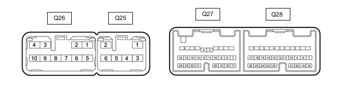
Disconnect the Q27 and Q28 position control ECU assembly connectors.
-
Measure the voltage and resistance according to the value(s) in the table below.
Terminal No. (Symbol) Wiring Color Terminal Description Condition Specified Condition Q27-1 (+B2) - Body ground W - Body ground Auxiliary battery power supply Power switch off 11 to 14 V Q27-2 (+B1) - Body ground W - Body ground Auxiliary battery power supply Power switch off 11 to 14 V Q28-1 (GND2) - Body ground W-B - Body ground Ground Always Below 1 Ω Q28-2 (GND1) - Body ground W-B - Body ground Ground Always Below 1 Ω Q28-18 (SYSB) - Body ground System power source Power switch off 11 to 14 V Q28-19 (IG) - Body ground SB - Body ground Ignition power supply Power switch off Below 1 V Power switch on (IG) 11 to 14 V Q28-20 (DBCL) - Body ground BR - Body ground Driver seat belt buckle switch signal Driver seat belt unfastened 10 kΩ or higher Driver seat belt fastened Below 1 Ω Q28-21 (DRDC) - Body ground V - Body ground Driver seat belt tension reducer signal Power switch on (IG) 11 to 14 V -
Reconnect the Q27 and Q28 position control ECU assembly connectors.
-
Measure the voltage and resistance according to the value(s) in the table below.
Terminal No. (Symbol) Wiring Color Terminal Description Condition Specified Condition Q25-3 (HD-) - Body ground LG - Body ground Headrest motor signal (rearward) Headrest adjuster switch off Below 1 V Headrest adjuster switch on (rearward) 11 to 14 V Q25-4 (H+) - Body ground L - Body ground Headrest motor signal (upward) Headrest switch off Below 1 V Headrest switch on (upward) 11 to 14 V Q258-5 (H-) - Body ground GR - Body ground Headrest motor signal (rearward) Headrest adjuster switch off Below 1 V Headrest switch on (downward) 11 to 14 V Q25-6 (HD+) - Body ground P - Body ground Headrest motor signal (forward) Headrest adjuster switch off Below 1 V Headrest adjuster switch on (forward) 11 to 14 V Q26-1 (CUS-) - Body ground B - Body ground Cushion motor signal (rearward) Cushion switch off Below 1 V Cushion switch on (rearward) 11 to 14 V Q26-2 (LFT-) - Body ground B - Body ground Rear lifter motor signal (downward) Rear lifter switch off Below 1 V Rear lifter switch on (downward) 11 to 14 V Q26-3 (CUS+) - Body ground R - Body ground Cushion motor signal (forward) Cushion switch off Below 1 V Cushion switch on (forward) 11 to 14 V Q26-5 (RCL-) - Body ground B - Body ground Reclining motor signal (rearward) Reclining adjuster switch off Below 1 V Reclining switch on (downward) 11 to 14 V Q26-6 (FRV-) - Body ground B - Body ground Front tilt motor signal (downward) Front vertical switch off Below 1 V Front vertical switch on (rearward) 11 to 14 V Q26-7 (FRV+) - Body ground R - Body ground Front vertical motor signal (upward) Front vertical switch off Below 1 V Front vertical switch on (upward) 11 to 14 V Q26-8 (RCL+) - Body ground R - Body ground Reclining motor signal (upward) Reclining switch off Below 1 V Reclining switch on (upward) 11 to 14 V Q26-29 (LFT+) - Body ground B - Body ground Rear lifter motor signal (upward) Rear lifter switch off Below 1 V Rear lifter switch on (upward) 11 to 14 V Q27-3 (RCLF) - Body ground W - Body ground Reclining switch signal (forward) Reclining switch off 11 to 14 V Reclining switch on (forward) Below 1 V Q27-4 (LVU) - Body ground L - Body ground Lumbar support adjuster switch signal (upward) Lumbar support adjuster switch off 11 to 14 V Lumbar support adjuster switch on (upward) Below 1 V Q27-7 (CUSF) - Body ground V - Body ground Cushion switch signal (forward) Cushion switch off 11 to 14 V Cushion switch on (forward) Below 1 V Q27-8 (CUSR) - Body ground GR - Body ground Cushion switch signal (rearward) Cushion switch off 11 to 14 V Cushion switch on (rearward) Below 1 V Q27-9 (LFTU) - Body ground BR - Body ground Rear lifter switch signal (upward) Rear lifter switch off 11 to 14 V Rear lifter switch on (upward) Below 1 V Q27-10 (LFTD) - Body ground Y - Body ground Rear lifter switch signal (downward) Rear lifter switch off 11 to 14 V Rear lifter switch on (downward) Below 1 V Q27-11 (RCLR) - Body ground B - Body ground Power seat switch LH (slide switch (forward)) signal Reclining switch off 11 to 14 V Reclining switch on (rearward) Below 1 V Q27-12 (FRVU) - Body ground GR - Body ground Front vertical switch signal (upward) Front vertical switch off 11 to 14 V Front vertical switch on (upward) Below 1 V Q27-13 (LVD) - Body ground LG - Body ground Lumbar support adjuster switch signal (downward) Lumbar support adjuster switch off 11 to 14 V Lumbar support adjuster switch on (downward) Below 1 V Q27-14 (LFLF) - Body ground Y - Body ground Lumbar support adjuster switch signal (forward) Lumbar support adjuster switch off 11 to 14 V Lumbar support adjuster switch on (forward) Below 1 V Q27-19 (SLDF) - Body ground R - Body ground Slide switch signal (forward) Slide switch off 11 to 14 V Slide switch on (forward) Below 1 V Q27-20 (SLDR) - Body ground G - Body ground Slide switch signal (rearward) Slide switch off 11 to 14 V Slide switch on (rearward) Below 1 V Q27-21 (FRVD) - Body ground BR - Body ground Front vertical switch signal (downward) Front vertical switch off 11 to 14 V Front vertical switch on (downward) Below 1 V Q27-22 (LFLR) - Body ground SB - Body ground Lumbar support adjuster switch signal (rearward) Lumbar support adjuster switch off 11 to 14 V Lumbar support adjuster switch on (rearward) Below 1 V Q27-24 (EMVS) - Body ground BR - Body ground Integration control and panel switch signal Integration control and panel switch off 11 to 14 V Integration control and panel switch on Below 1 V Q28-3 (POMG) ←→ Q28-4 (POM) V - W-B Lumbar support pump sub-assembly signal Lumbar support pump sub-assembly operating 11 to 14 V Q28-5 (SLD+) - Body ground R - Body ground Slide motor signal (forward) Slide switch off Below 1 V Slide switch on (forward) 11 to 14 V Q28-6 (SLD-) - Body ground B - Body ground Slide motor signal (rearward) Slide switch off Below 1 V Slide switch on (rearward) 11 to 14 V Q28-7 (LIN) - Body ground SB - Body ground LIN communication line Power switch on (IG) Pulse generation Q28-10 (SSHD) - Body ground Y - Body ground Headrest position signal Headrest up/down function operating Pulse generation Q28-13 (SSRC) - Body ground P - Body ground Cushion position signal Cushion length function operating Pulse generation Q28-14 (SSRH) - Body ground G - Body ground Headrest position signal Headrest front/rear function operating Pulse generation Q28-15 (SSRL) - Body ground LG - Body ground Rear lifter position signal Rear lifter function operating Pulse generation Q28-16 (SGND) - Body ground GR - Body ground Sensor ground Always Below 1 Ω Q28-24 (SSRR) - Body ground L - Body ground Reclining position signal Reaclining function operating Pulse generation Q28-25 (SSFV) - Body ground GR - Body ground Front tilt position signal Front tilt function operating Pulse generation Q28-26 (SSRS) - Body ground BR - Body ground Slide position signal Slide function operating Pulse generation
-
-
for RHD:

-
Disconnect the Q7 and Q8 position control ECU assembly connectors.
-
Measure the voltage and resistance according to the value(s) in the table below.
Terminal No. (Symbol) Wiring Color Terminal Description Condition Specified Condition Q7-1 (+B2) - Body ground W - Body ground Auxiliary battery power supply Power switch off 11 to 14 V Q7-2 (+B1) - Body ground W - Body ground Auxiliary battery power supply Power switch off 11 to 14 V Q8-1 (GND2) - Body ground W-B - Body ground Ground Always Below 1 Ω Q8-2 (GND1) - Body ground W-B - Body ground Ground Always Below 1 Ω Q8-18 (SYSB) - Body ground System power source Power switch off 11 to 14 V Q8-19 (IG) - Body ground SB - Body ground Ignition power supply Power switch off Below 1 V Power switch on (IG) 11 to 14 V Q8-20 (DBCL) - Body ground BR - Body ground Driver seat belt buckle switch signal Driver seat belt unfastened 10 kΩ or higher Driver seat belt fastened Below 1 Ω Q8-21 (DRDC) - Body ground V - Body ground Driver seat belt tension reducer signal Power switch on (IG) 11 to 14 V -
Reconnect the Q7and Q8 position control ECU assembly connectors.
-
Measure the voltage and resistance according to the value(s) in the table below.
Terminal No. (Symbol) Wiring Color Terminal Description Condition Specified Condition Q5-3 (HD-) - Body ground LG - Body ground Headrest motor signal (rearward) Headrest adjuster switch off Below 1 V Headrest adjuster switch on (rearward) 11 to 14 V Q5-4 (H+) - Body ground L - Body ground Headrest motor signal (upward) Headrest switch off Below 1 V Headrest switch on (upward) 11 to 14 V Q5-5 (H-) - Body ground GR - Body ground Headrest motor signal (rearward) Headrest adjuster switch off Below 1 V Headrest switch on (downward) 11 to 14 V Q2-6 (HD+) - Body ground P - Body ground Headrest motor signal (forward) Headrest adjuster switch off Below 1 V Headrest adjuster switch on (forward) 11 to 14 V Q6-1 (CUS-) - Body ground B - Body ground Cushion motor signal (rearward) Cushion switch off Below 1 V Cushion switch on (rearward) 11 to 14 V Q6-2 (LFT-) - Body ground B - Body ground Rear lifter motor signal (downward) Rear lifter switch off Below 1 V Rear lifter switch on (downward) 11 to 14 V Q6-3 (CUS+) - Body ground R - Body ground Cushion motor signal (forward) Cushion switch off Below 1 V Cushion switch on (forward) 11 to 14 V Q6-5 (RCL-) - Body ground B - Body ground Reclining motor signal (rearward) Reclining adjuster switch off Below 1 V Reclining switch on (downward) 11 to 14 V Q6-6 (FRV-) - Body ground B - Body ground Front tilt motor signal (downward) Front vertical switch off Below 1 V Front vertical switch on (rearward) 11 to 14 V Q6-7 (FRV+) - Body ground R - Body ground Front vertical motor signal (upward) Front vertical switch off Below 1 V Front vertical switch on (upward) 11 to 14 V Q6-8 (RCL+) - Body ground R - Body ground Reclining motor signal (upward) Reclining switch off Below 1 V Reclining switch on (upward) 11 to 14 V Q6-29 (LFT+) - Body ground B - Body ground Rear lifter motor signal (upward) Rear lifter switch off Below 1 V Rear lifter switch on (upward) 11 to 14 V Q7-3 (RCLF) - Body ground W - Body ground Reclining switch signal (forward) Reclining switch off 11 to 14 V Reclining switch on (forward) Below 1 V Q7-4 (LVU) - Body ground L - Body ground Lumbar support adjuster switch signal (upward) Lumbar support adjuster switch off 11 to 14 V Lumbar support adjuster switch on (upward) Below 1 V Q7-7 (CUSF) - Body ground V - Body ground Cushion switch signal (forward) Cushion switch off 11 to 14 V Cushion switch on (forward) Below 1 V Q7-8 (CUSR) - Body ground GR - Body ground Cushion switch signal (rearward) Cushion switch off 11 to 14 V Cushion switch on (rearward) Below 1 V Q7-9 (LFTU) - Body ground BR - Body ground Rear lifter switch signal (upward) Rear lifter switch off 11 to 14 V Rear lifter switch on (upward) Below 1 V Q7-10 (LFTD) - Body ground Y - Body ground Rear lifter switch signal (downward) Rear lifter switch off 11 to 14 V Rear lifter switch on (downward) Below 1 V Q7-11 (RCLR) - Body ground B - Body ground Power seat switch LH (slide switch (forward)) signal Reclining switch off 11 to 14 V Reclining switch on (rearward) Below 1 V Q7-12 (FRVU) - Body ground GR - Body ground Front vertical switch signal (upward) Front vertical switch off 11 to 14 V Front vertical switch on (upward) Below 1 V Q7-13 (LVD) - Body ground LG - Body ground Lumbar support adjuster switch signal (downward) Lumbar support adjuster switch off 11 to 14 V Lumbar support adjuster switch on (downward) Below 1 V Q7-14 (LFLF) - Body ground Y - Body ground Lumbar support adjuster switch signal (forward) Lumbar support adjuster switch off 11 to 14 V Lumbar support adjuster switch on (forward) Below 1 V Q7-19 (SLDF) - Body ground R - Body ground Slide switch signal (forward) Slide switch off 11 to 14 V Slide switch on (forward) Below 1 V Q7-20 (SLDR) - Body ground G - Body ground Slide switch signal (rearward) Slide switch off 11 to 14 V Slide switch on (rearward) Below 1 V Q7-21 (FRVD) - Body ground BR - Body ground Front vertical switch signal (downward) Front vertical switch off 11 to 14 V Front vertical switch on (downward) Below 1 V Q7-22 (LFLR) - Body ground SB - Body ground Lumbar support adjuster switch signal (rearward) Lumbar support adjuster switch off 11 to 14 V Lumbar support adjuster switch on (rearward) Below 1 V Q7-24 (EMVS) - Body ground BR - Body ground Integration control and panel switch signal Integration control and panel switch off 11 to 14 V Integration control and panel switch on Below 1 V Q8-3 (POMG) ←→ Q8-4 (POM) V - W-B Lumbar support pump sub-assembly signal Lumbar support pump sub-assembly operating 11 to 14 V Q8-5 (SLD+) - Body ground R - Body ground Slide motor signal (forward) Slide switch off Below 1 V Slide switch on (forward) 11 to 14 V Q8-6 (SLD-) - Body ground B - Body ground Slide motor signal (rearward) Slide switch off Below 1 V Slide switch on (rearward) 11 to 14 V Q8-7 (LIN) - Body ground SB - Body ground LIN communication line Power switch on (IG) Pulse generation Q8-10 (SSHD) - Body ground Y - Body ground Headrest position signal Headrest up/down function operating Pulse generation Q8-13 (SSRC) - Body ground P - Body ground Cushion position signal Cushion length function operating Pulse generation Q8-14 (SSRH) - Body ground G - Body ground Headrest position signal Headrest front/rear function operating Pulse generation Q8-15 (SSRL) - Body ground LG - Body ground Rear lifter position signal Rear lifter function operating Pulse generation Q8-16 (SGND) - Body ground GR - Body ground Sensor ground Always Below 1 Ω Q8-24 (SSRR) - Body ground L - Body ground Reclining position signal Reaclining function operating Pulse generation Q8-25 (SSFV) - Body ground GR - Body ground Front tilt position signal Front tilt function operating Pulse generation Q8-26 (SSRS) - Body ground BR - Body ground Slide position signal Slide function operating Pulse generation
-
-
-
CHECK NO. 2 POSITION CONTROL ECU ASSEMBLY
-
for LHD:
-
Reconnect the Q7and Q8 No. 2 position control ECU assembly connectors.
-
Measure the voltage and resistance according to the value(s) in the table below.
Terminal No. (Symbol) Wiring Color Terminal Description Condition Specified Condition Q7-1 (+B2) - Body ground W - Body ground Auxiliary battery power supply Power switch off 11 to 14 V Q7-2 (+B1) - Body ground W - Body ground Auxiliary battery power supply Power switch off 11 to 14 V Q8-1 (GND2) - Body ground W-B - Body ground Ground Always Below 1 Ω Q8-2 (GND1) - Body ground W-B - Body ground Ground Always Below 1 Ω Q8-18 (SYSB) - Body ground System power source Power switch off 11 to 14 V Q8-19 (IG) - Body ground SB - Body ground Ignition power supply Power switch off Below 1 V Power switch on (IG) 11 to 14 V Q8-20 (DBCL) - Body ground BR - Body ground Front passenger seat belt buckle switch signal Front passenger seat belt unfastened 10 kΩ or higher Front passenger seat belt fastened Below 1 Ω Q8-21 (DRDC) - Body ground V - Body ground Front passenger seat belt tension reducer signal Power switch on (IG) 11 to 14 V -
Reconnect the Q7and Q8 No. 2 No. 2 position control ECU assembly connectors.
-
Measure the voltage and resistance according to the value(s) in the table below.
Terminal No. (Symbol) Wiring Color Terminal Description Condition Specified Condition Q5-3 (HD-) - Body ground LG - Body ground Headrest motor signal (rearward) Headrest adjuster switch off Below 1 V Headrest adjuster switch on (rearward) 11 to 14 V Q5-4 (H+) - Body ground L - Body ground Headrest motor signal (upward) Headrest switch off Below 1 V Headrest switch on (upward) 11 to 14 V Q5-5 (H-) - Body ground GR - Body ground Headrest motor signal (rearward) Headrest adjuster switch off Below 1 V Headrest switch on (downward) 11 to 14 V Q2-6 (HD+) - Body ground P - Body ground Headrest motor signal (forward) Headrest adjuster switch off Below 1 V Headrest adjuster switch on (forward) 11 to 14 V Q6-1 (CUS-) - Body ground B - Body ground Cushion motor signal (rearward) Cushion switch off Below 1 V Cushion switch on (rearward) 11 to 14 V Q6-2 (LFT-) - Body ground B - Body ground Rear lifter motor signal (downward) Rear lifter switch off Below 1 V Rear lifter switch on (downward) 11 to 14 V Q6-3 (CUS+) - Body ground R - Body ground Cushion motor signal (forward) Cushion switch off Below 1 V Cushion switch on (forward) 11 to 14 V Q6-5 (RCL-) - Body ground B - Body ground Reclining motor signal (rearward) Reclining adjuster switch off Below 1 V Reclining switch on (downward) 11 to 14 V Q6-6 (FRV-) - Body ground B - Body ground Front tilt motor signal (downward) Front vertical switch off Below 1 V Front vertical switch on (rearward) 11 to 14 V Q6-7 (FRV+) - Body ground R - Body ground Front vertical motor signal (upward) Front vertical switch off Below 1 V Front vertical switch on (upward) 11 to 14 V Q6-8 (RCL+) - Body ground R - Body ground Reclining motor signal (upward) Reclining switch off Below 1 V Reclining switch on (upward) 11 to 14 V Q6-29 (LFT+) - Body ground B - Body ground Rear lifter motor signal (upward) Rear lifter switch off Below 1 V Rear lifter switch on (upward) 11 to 14 V Q7-3 (RCLF) - Body ground W - Body ground Reclining switch signal (forward) Reclining switch off 11 to 14 V Reclining switch on (forward) Below 1 V Q7-4 (LVU) - Body ground L - Body ground Lumbar support adjuster switch signal (upward) Lumbar support adjuster switch off 11 to 14 V Lumbar support adjuster switch on (upward) Below 1 V Q7-7 (CUSF) - Body ground V - Body ground Cushion switch signal (forward) Cushion switch off 11 to 14 V Cushion switch on (forward) Below 1 V Q7-8 (CUSR) - Body ground GR - Body ground Cushion switch signal (rearward) Cushion switch off 11 to 14 V Cushion switch on (rearward) Below 1 V Q7-9 (LFTU) - Body ground BR - Body ground Rear lifter switch signal (upward) Rear lifter switch off 11 to 14 V Rear lifter switch on (upward) Below 1 V Q7-10 (LFTD) - Body ground Y - Body ground Rear lifter switch signal (downward) Rear lifter switch off 11 to 14 V Rear lifter switch on (downward) Below 1 V Q7-11 (RCLR) - Body ground B - Body ground Power seat switch LH (slide switch (forward)) signal Reclining switch off 11 to 14 V Reclining switch on (rearward) Below 1 V Q7-12 (FRVU) - Body ground GR - Body ground Front vertical switch signal (upward) Front vertical switch off 11 to 14 V Front vertical switch on (upward) Below 1 V Q7-13 (LVD) - Body ground LG - Body ground Lumbar support adjuster switch signal (downward) Lumbar support adjuster switch off 11 to 14 V Lumbar support adjuster switch on (downward) Below 1 V Q7-14 (LFLF) - Body ground Y - Body ground Lumbar support adjuster switch signal (forward) Lumbar support adjuster switch off 11 to 14 V Lumbar support adjuster switch on (forward) Below 1 V Q7-19 (SLDF) - Body ground R - Body ground Slide switch signal (forward) Slide switch off 11 to 14 V Slide switch on (forward) Below 1 V Q7-20 (SLDR) - Body ground G - Body ground Slide switch signal (rearward) Slide switch off 11 to 14 V Slide switch on (rearward) Below 1 V Q7-21 (FRVD) - Body ground BR - Body ground Front vertical switch signal (downward) Front vertical switch off 11 to 14 V Front vertical switch on (downward) Below 1 V Q7-22 (LFLR) - Body ground SB - Body ground Lumbar support adjuster switch signal (rearward) Lumbar support adjuster switch off 11 to 14 V Lumbar support adjuster switch on (rearward) Below 1 V Q8-3 (POMG) ←→ Q8-4 (POM) V - W-B Lumbar support pump sub-assembly signal Lumbar support pump sub-assembly operating 11 to 14 V Q8-5 (SLD+) - Body ground R - Body ground Slide motor signal (forward) Slide switch off Below 1 V Slide switch on (forward) 11 to 14 V Q8-6 (SLD-) - Body ground B - Body ground Slide motor signal (rearward) Slide switch off Below 1 V Slide switch on (rearward) 11 to 14 V Q8-7 (LIN) - Body ground SB - Body ground LIN communication line Power switch on (IG) Pulse generation Q8-10 (SSHD) - Body ground Y - Body ground Headrest position signal Headrest up/down function operating Pulse generation Q8-13 (SSRC) - Body ground P - Body ground Cushion position signal Cushion length function operating Pulse generation Q8-14 (SSRH) - Body ground G - Body ground Headrest position signal Headrest front/rear function operating Pulse generation Q8-15 (SSRL) - Body ground LG - Body ground Rear lifter position signal Rear lifter function operating Pulse generation Q8-16 (SGND) - Body ground GR - Body ground Sensor ground Always Below 1 Ω Q8-24 (SSRR) - Body ground L - Body ground Reclining position signal Reaclining function operating Pulse generation Q8-25 (SSFV) - Body ground GR - Body ground Front tilt position signal Front tilt function operating Pulse generation Q8-26 (SSRS) - Body ground BR - Body ground Slide position signal Slide function operating Pulse generation
-
-
for RHD:
-
Disconnect the Q27 and Q28 No. 2 position control ECU assembly connectors.
-
Measure the voltage and resistance according to the value(s) in the table below.
Terminal No. (Symbol) Wiring Color Terminal Description Condition Specified Condition Q27-1 (+B2) - Body ground W - Body ground Auxiliary battery power supply Power switch off 11 to 14 V Q27-2 (+B1) - Body ground W - Body ground Auxiliary battery power supply Power switch off 11 to 14 V Q28-1 (GND2) - Body ground W-B - Body ground Ground Always Below 1 Ω Q28-2 (GND1) - Body ground W-B - Body ground Ground Always Below 1 Ω Q28-18 (SYSB) - Body ground System power source Power switch off 11 to 14 V Q28-19 (IG) - Body ground SB - Body ground Ignition power supply Power switch off Below 1 V Power switch on (IG) 11 to 14 V Q28-20 (DBCL) - Body ground BR - Body ground Front passenger seat belt buckle switch signal Front passenger seat belt unfastened 10 kΩ or higher Front passenger seat belt fastened Below 1 Ω Q28-21 (DRDC) - Body ground V - Body ground Front passenger seat belt tension reducer signal Power switch on (IG) 11 to 14 V -
Reconnect the Q27 and Q28 No. 2 position control ECU assembly connectors.
-
Measure the voltage and resistance according to the value(s) in the table below.
Terminal No. (Symbol) Wiring Color Terminal Description Condition Specified Condition Q25-3 (HD-) - Body ground LG - Body ground Headrest motor signal (rearward) Headrest adjuster switch off Below 1 V Headrest adjuster switch on (rearward) 11 to 14 V Q25-4 (H+) - Body ground L - Body ground Headrest motor signal (upward) Headrest switch off Below 1 V Headrest switch on (upward) 11 to 14 V Q258-5 (H-) - Body ground GR - Body ground Headrest motor signal (rearward) Headrest adjuster switch off Below 1 V Headrest switch on (downward) 11 to 14 V Q25-6 (HD+) - Body ground P - Body ground Headrest motor signal (forward) Headrest adjuster switch off Below 1 V Headrest adjuster switch on (forward) 11 to 14 V Q26-1 (CUS-) - Body ground B - Body ground Cushion motor signal (rearward) Cushion switch off Below 1 V Cushion switch on (rearward) 11 to 14 V Q26-2 (LFT-) - Body ground B - Body ground Rear lifter motor signal (downward) Rear lifter switch off Below 1 V Rear lifter switch on (downward) 11 to 14 V Q26-3 (CUS+) - Body ground R - Body ground Cushion motor signal (forward) Cushion switch off Below 1 V Cushion switch on (forward) 11 to 14 V Q26-5 (RCL-) - Body ground B - Body ground Reclining motor signal (rearward) Reclining adjuster switch off Below 1 V Reclining switch on (downward) 11 to 14 V Q26-6 (FRV-) - Body ground B - Body ground Front tilt motor signal (downward) Front vertical switch off Below 1 V Front vertical switch on (rearward) 11 to 14 V Q26-7 (FRV+) - Body ground R - Body ground Front vertical motor signal (upward) Front vertical switch off Below 1 V Front vertical switch on (upward) 11 to 14 V Q26-8 (RCL+) - Body ground R - Body ground Reclining motor signal (upward) Reclining switch off Below 1 V Reclining switch on (upward) 11 to 14 V Q26-29 (LFT+) - Body ground B - Body ground Rear lifter motor signal (upward) Rear lifter switch off Below 1 V Rear lifter switch on (upward) 11 to 14 V Q27-3 (RCLF) - Body ground W - Body ground Reclining switch signal (forward) Reclining switch off 11 to 14 V Reclining switch on (forward) Below 1 V Q27-4 (LVU) - Body ground L - Body ground Lumbar support adjuster switch signal (upward) Lumbar support adjuster switch off 11 to 14 V Lumbar support adjuster switch on (upward) Below 1 V Q27-7 (CUSF) - Body ground V - Body ground Cushion switch signal (forward) Cushion switch off 11 to 14 V Cushion switch on (forward) Below 1 V Q27-8 (CUSR) - Body ground GR - Body ground Cushion switch signal (rearward) Cushion switch off 11 to 14 V Cushion switch on (rearward) Below 1 V Q27-9 (LFTU) - Body ground BR - Body ground Rear lifter switch signal (upward) Rear lifter switch off 11 to 14 V Rear lifter switch on (upward) Below 1 V Q27-10 (LFTD) - Body ground Y - Body ground Rear lifter switch signal (downward) Rear lifter switch off 11 to 14 V Rear lifter switch on (downward) Below 1 V Q27-11 (RCLR) - Body ground B - Body ground Power seat switch LH (slide switch (forward)) signal Reclining switch off 11 to 14 V Reclining switch on (rearward) Below 1 V Q27-12 (FRVU) - Body ground GR - Body ground Front vertical switch signal (upward) Front vertical switch off 11 to 14 V Front vertical switch on (upward) Below 1 V Q27-13 (LVD) - Body ground LG - Body ground Lumbar support adjuster switch signal (downward) Lumbar support adjuster switch off 11 to 14 V Lumbar support adjuster switch on (downward) Below 1 V Q27-14 (LFLF) - Body ground Y - Body ground Lumbar support adjuster switch signal (forward) Lumbar support adjuster switch off 11 to 14 V Lumbar support adjuster switch on (forward) Below 1 V Q27-19 (SLDF) - Body ground R - Body ground Slide switch signal (forward) Slide switch off 11 to 14 V Slide switch on (forward) Below 1 V Q27-20 (SLDR) - Body ground G - Body ground Slide switch signal (rearward) Slide switch off 11 to 14 V Slide switch on (rearward) Below 1 V Q27-21 (FRVD) - Body ground BR - Body ground Front vertical switch signal (downward) Front vertical switch off 11 to 14 V Front vertical switch on (downward) Below 1 V Q27-22 (LFLR) - Body ground SB - Body ground Lumbar support adjuster switch signal (rearward) Lumbar support adjuster switch off 11 to 14 V Lumbar support adjuster switch on (rearward) Below 1 V Q28-3 (POMG) ←→ Q28-4 (POM) V - W-B Lumbar support pump sub-assembly signal Lumbar support pump sub-assembly operating 11 to 14 V Q28-5 (SLD+) - Body ground R - Body ground Slide motor signal (forward) Slide switch off Below 1 V Slide switch on (forward) 11 to 14 V Q28-6 (SLD-) - Body ground B - Body ground Slide motor signal (rearward) Slide switch off Below 1 V Slide switch on (rearward) 11 to 14 V Q28-7 (LIN) - Body ground SB - Body ground LIN communication line Power switch on (IG) Pulse generation Q28-10 (SSHD) - Body ground Y - Body ground Headrest position signal Headrest up/down function operating Pulse generation Q28-13 (SSRC) - Body ground P - Body ground Cushion position signal Cushion length function operating Pulse generation Q28-14 (SSRH) - Body ground G - Body ground Headrest position signal Headrest front/rear function operating Pulse generation Q28-15 (SSRL) - Body ground LG - Body ground Rear lifter position signal Rear lifter function operating Pulse generation Q28-16 (SGND) - Body ground GR - Body ground Sensor ground Always Below 1 Ω Q28-24 (SSRR) - Body ground L - Body ground Reclining position signal Reaclining function operating Pulse generation Q28-25 (SSFV) - Body ground GR - Body ground Front tilt position signal Front tilt function operating Pulse generation Q28-26 (SSRS) - Body ground BR - Body ground Slide position signal Slide function operating Pulse generation
-
-
-
CHECK FRONT MULTIPLEX NETWORK DOOR ECU (FOR DRIVER SEAT)
-
for LHD:

-
Disconnect the H31 front multiplex network door ECU LH connector.
-
Measure the voltage and resistance according to the value(s) in the table below.
Terminal No. (Symbol) Wiring Color Terminal Description Condition Specified Condition H31-3 (SIG) - Body ground B - Body ground Ignition power supply (IG signal) Power switch off → on (IG) Below 1 V → 11 to 14 V H31-4 (CPUB) - Body ground L - Body ground Auxiliary battery power supply Power switch off 11 to 14 V H31-6 (BDR) - Body ground R - Body ground Auxiliary battery power supply Power switch off 11 to 14 V H31-1 (GND) - Body ground W-B - Body ground Ground Always Below 1 Ω -
Reconnect the H31 front multiplex network door ECU LH connector.
-
Measure the voltage and resistance according to the value(s) in the table below.
Terminal No. (Symbol) Wiring Color Terminal Description Condition Specified Condition H31-24 (M3) - H31-26 (MSWE) V - W-B M3 switch signal for seat memory switch M3 switch on Below 1 V M3 switch off 11 to 14 V H31-23 (M2) - H31-26 (MSWE) G - W-B M2 switch signal for seat memory switch M2 switch on Below 1 V M2 switch off 11 to 14 V H31-22 (M1) - H31-26 (MSWE) BE - W-B M1 switch signal for seat memory switch M1 switch on Below 1 V M1 switch off 11 to 14 V H31-25 (MM) - H31-26 (MSWE) L - W-B SET switch signal for seat memory switch SET switch on Below 1 V SET switch off 11 to 14 V H31-26 (MSWE) - Body ground LA-BR - Body ground Ground Always Below 1 Ω
-
-
for RHD:

-
Disconnect the H12 front multiplex network door ECU RH connector.
-
Measure the voltage and resistance according to the value(s) in the table below.
Terminal No. (Symbol) Wiring Color Terminal Description Condition Specified Condition H12-3 (SIG) - Body ground B - Body ground Ignition power supply (IG signal) Power switch off → on (IG) Below 1 V → 11 to 14 V H12-4 (CPUB) - Body ground L - Body ground Auxiliary battery power supply Power switch off 11 to 14 V H12-6 (BDR) - Body ground R - Body ground Auxiliary battery power supply Power switch off 11 to 14 V H12-1 (GND) - Body ground W-B - Body ground Ground Always Below 1 Ω -
Reconnect the H12 front multiplex network door ECU LH connector.
-
Measure the voltage and resistance according to the value(s) in the table below.
Terminal No. (Symbol) Wiring Color Terminal Description Condition Specified Condition H12-24 (M3) - H12-26 (MSWE) V - W-B M3 switch signal for seat memory switch M3 switch on Below 1 V M3 switch off 11 to 14 V H12-23 (M2) - H12-26 (MSWE) G - W-B M2 switch signal for seat memory switch M2 switch on Below 1 V M2 switch off 11 to 14 V H12-22 (M1) - H12-26 (MSWE) BE - W-B M1 switch signal for seat memory switch M1 switch on Below 1 V M1 switch off 11 to 14 V H12-25 (MM) - H12-26 (MSWE) L - W-B SET switch signal for seat memory switch SET switch on Below 1 V SET switch off 11 to 14 V H12-26 (MSWE) - Body ground LA-BR - Body ground Ground Always Below 1 Ω
-
-
-
CHECK MAIN BODY ECU (MULTIPLEX NETWORK BODY ECU)
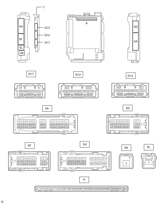
*1 Main Body ECU (Multiplex Network Body ECU) - -
-
Remove the main body ECU (multiplex network body ECU) from the instrument panel junction block assembly.
-
Connect the driver side junction block assembly.
-
Measure the voltage and resistance according to the value(s) in the table below.
Terminal No. (Symbol) Wiring Color Terminal Description Condition Specified Condition A-32 (IG) - Body ground Note - Body ground Ignition power supply Power switch on (IG) 11 to 14 V Power switch off Below 1 V A-31 (BECU) - Body ground Note - Body ground Auxiliary battery power supply Power switch off 11 to 14 V A-30 (ACC) - Body ground Note - Body ground ACC power supply Power switch on (ACC) 11 to 14 V Power switch off Below 1 V A-11 (GND1) - Body ground Note - Body ground Ground Always Below 1 Ω -
Install the main body ECU (multiplex network body ECU).
-
Measure the voltage and pulse according to the value(s) in the table below.
Terminal No. (Symbol) Wiring Color Terminal Description Condition Specified Condition G12-1 (FLCY) - Body ground R - Body ground Front door courtesy light switch LH input Front door LH open Below 1 V Front door LH closed 4.7 to 5.3 V G12-6 (FRCY) - Body ground SB - Body ground*1
R - Body ground*2
Front door courtesy light assembly RH INput Front door RH open Below 1 V Front door RH closed 4.7 to 5.3 V
-
*1: for LHD
-
*2: for RHD
-
-