CAUTION / NOTICE / HINT
-
Use the same procedure for RHD and LHD vehicles.
-
The procedure listed below is for LHD vehicles.
-
Use the same procedure for the RH and LH sides.
-
The procedure listed below is for the LH side.
PROCEDURE
- Click here
INSTALL NO. 2 SIDE AIRBAG SENSOR ASSEMBLY
-
Check that the power switch is off.
-
Check that the cable is disconnected from the negative (-) auxiliary battery terminal.
CAUTION:
-
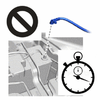
Wait at least 90 seconds after disconnecting the cable from the negative (-) auxiliary battery terminal to disable the SRS system.
-
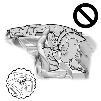
If this procedure is performed without disconnecting the negative (-) auxiliary battery terminal of the battery, the airbag may deploy even if an impact is applied only to the side airbag sensor assembly LH. Therefore, make sure that the negative (-) auxiliary battery terminal of the battery is disconnected before performing this procedure.
-
-
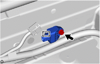
Attach the guide to hold the No. 2 side airbag sensor assembly LH in place.
-
Install the bolt.
9.0 N*m 92 kgf*cm 80 in.*lbf Note:
-
If the No. 2 side airbag sensor assembly LH has been dropped, replace it with a new one.
-
When installing the No. 2 side airbag sensor assembly LH, be careful that the SRS wiring does not interfere with or is not pinched between other parts.
-
Tighten the bolt while holding the No. 2 side airbag sensor assembly LH because the No. 2 side airbag sensor assembly LH guide is easily damaged.
-
-
Check that there is no looseness in the installation parts of the No. 2 side airbag sensor assembly LH.
-
Connect the airbag connector.
Note:When connecting any airbag connector, take care not to damage the airbag wire harness.
-
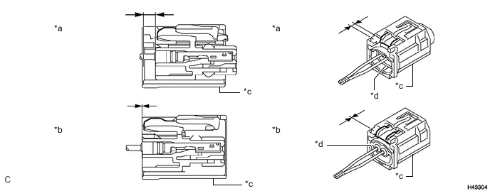
*a Correct *b Incorrect *c CPA *d Housing Lock Before connecting the connector, check that the position of the housing lock is correct as shown in the illustration.
-
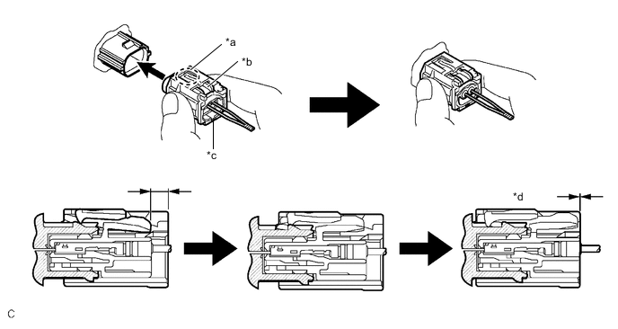
*a CPA Upper Part *b Housing Lock *c CPA *d Connection is Completed While holding the CPA be sure to engage the connectors until they are locked and check that the CPA is in its original position (when locking, make sure that a click sound can be heard).
Note:Do not push down the upper part of the CPA shown in the illustration when connecting the airbag connector.
-
-
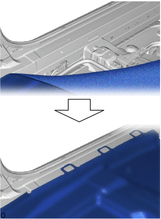
Return the floor carpet to its original position.
-
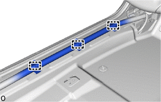
Attach the wire harness clamp.
-
- Click here
INSTALL LOWER CENTER PILLAR GARNISH LH
- Click here
INSTALL REAR DOOR SCUFF PLATE LH
- Click here
INSTALL COWL SIDE TRIM BOARD LH
- Click here
INSTALL FRONT DOOR SCUFF PLATE LH
- Click here
INSTALL FRONT SEAT ASSEMBLY LH
- Click here
PERFORM DIAGNOSTIC SYSTEM CHECK
- Click here
CHECK SRS WARNING LIGHT
- Click here
PERFORM SYSTEM CALIBRATION